


Quick Start Guide
Mio Modero DMS Keypad
metallic
Overview
The Mio Modero DMS device family provides a wide range of control capabilities in the
form of user specified buttons that are functional yet recherché.
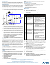
Mio Modero DMS keypads are equipped with an LCD menu display with 8
pushbuttons for navigation and menu selection.
Specifications
Dynamic Menu System
Using the KeypadBuilder application available for download from www.amx.com, the
Mio Modero DMS is programmed with a Dynamic Menu System (DMS) that is
navigated via the 8 pushbuttons and LCD display area. See the KeypadBuilder
Instruction Manual for more information on programming Mio Modero DMS devices.
Installation
Note: To avoid any damage to the electronic component, installation must be
performed in an ESD safe environment. The device and conduit box must have an
Earth ground.
The installation section addresses the mounting and wiring of the Mio Modero DMS.
After you have completed the installation you must consult Necessary Device Setup.
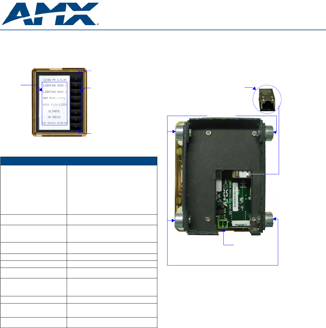
Rear Components
The rear components of the Mio Modero DMS (FIG. 2) are as follows:
Connections and Wiring
The Mio Modero DMS device is powered either via 12VDC or Power over Ethernet
(PoE). If both the 12 VDC and PoE power sources are connected, by default the
device draws power from the 12 VDC. If the 12 VDC source is disconnected, the PoE
automatically supplies power after a device reboot.
Note: Do not connect power to the Mio Modero DMS until the wiring is complete.
Preparing captive wires for the 2-pin 3.5 mm mini-Phoenix connector
You will need a wire stripper, and flat-blade screwdriver to prepare and connect the
captive wires.
1. Strip 0.25 inch (6.35 mm) of wire insulation off all wires.
2. Insert each wire into the appropriate opening on the connector according to the
wiring diagrams and connector types described in this section.
3. Turn the screws clockwise to secure the wires in the connector.
Note: Do not over-torque the screws; doing so can bend the seating pins and damage
the connector.
Using the PSN NetLinx connector for power
The PWR and GND wires from the 12 VDC power supply must be connected to the
corresponding location on the 2-pin 3.5 mm mini-Phoenix connector (See the
KeypadBuilder Instruction Manual for an illustration).
1. Insert the PWR and GND wires on the terminal end of a PSN 2-pin 3.5 mm mini-
Phoenix cable. Match the wiring locations of the +/- on both the power supply
and the terminal connector.
2. Tighten the clamp to secure the two wires.
3. Verify the connection of the 2-pin 3.5 mm mini-Phoenix to the power supply.
Using the Ethernet port for power (PoE)
Connect your CAT5/CAT6 Ethernet cable to the port shown in FIG. 2. (See the Mio
Modero DMS & Mio Modero DMS Pinnacle instruction manual for an illustration and
cable pinouts).
FIG. 1
Mio Modero DMS Device Family
Mio Modero DMS (FG2408-01XX) Specifications
Power 12 VDC / PoE:
Maximum power consumption (PoE): • 5.5 Watts
Maximum startup (rush) current (PoE):
• 150 mA @ 50 VDC
Maximum continuous current (PoE):
• 100 mA @ 50 VDC
Maximum power consumption (DC):
• 5.0 Watts
Maximum startup (rush) current (DC):
• 525 mA @ 13.5 VDC
Maximum continuous current (DC):
• 350 mA @ 13.5 VDC
Front Panel Components: • LCD display
• 8 pushbuttons
Rear Panel Connectors: • Ethernet Port (PoE)
• 2-pin 3.5 mm mini-Phoenix (female) connector
• 4 Magnetic Posts
• Ground wire
Dimensions (HWD):
(inside of conduit box)
• 6.25 (158.8 mm) x 3.50 (91.4 mm) x 3.93 (99.7 mm)
Supported Fonts: Only True Type Fonts
Weight (range):
• Device - .55 lbs (.25 kg)
Operating Environment: • Operating Temperature: 0° to 40° C (32° to 104° F)
• Storage Temperature: -10° to 60° C (14° to 140° F)
Mounting: The Mio Modero DMS is installed in one of three ways:
• Rough-in mounting
• Expansion clips for pressure mounting
• No tabs for brick and mortar mounting
Available Color Schemes: Gold (GL), Silver (SL)
Included Accessories: • 2-pin 3.5 mm mini-Phoenix connector (41-5025)
• Conduit box (FG039-11)
• Mounting kit (KA2250-01)
Other AMX Equipment: • NXA-ENET24PoE: Managed Ethernet Switch, Power
Over Ethernet (FG2178-61)
Menu Up
Menu select
pushbuttons
Menu Down
Menu items
FIG. 2 Mio Modero DMS Rear Components
2-pin
3.5 mm
(female)
Ethernet Port
(Front View)
(PoE)
connector
mini-Phoenix
Magnetic Posts