


Installation Guide
MAX-HT Home Theater Servers (HT04/HT12)
MAX-HT04 & MAX-HT12 Home Theater Servers
The MAX-HT Home Theater Servers (FIG. 1) feature a robust internal hard drive
system that allows you to efficiently manage hundreds of DVDs and CDs. There are
two models of HT servers available, with different storage capacities:
• MAX-HT04 (FG 2178 - 14)
• MAX-HT12 (FG 2178 - 15)
MAX-HT Servers support multiple MAX-AVP Audio-Video Players and/or MAX-AVM
Audio/Video modules via Ethernet (up to 25 total), and up to 2 MAX-AOM Audio-Only
modules via USB.
Product Specifications
Related Documents
The following AMX documents provide additional information on the HT Servers and
related devices, and are available online at www.amx.com:
• Refer to the WinMAX Software manual for details on using WinMAX to add/
remove DVD/CD content on the server, and control playback.
• Refer to the MDL-200 Multi-Disc Loader System manual for details on using the
MDL200 Multi-Disc Loader System to bulk-load large numbers of discs to the
server.
• Refer to the MAX Servers manual for additional device information and configu-
ration instructions for MAX servers, including instructions on rack-mounting,
changing the region code setting on the server’s internal DVD drive and a full
description of the options in the MAX Admin Menu.
• Refer to the MAX-AOM, MAX-AVM and MAX-AVP Installation Guides and
Instruction Manuals for detailed product information.
• Refer to the Setting Up a 4-Zone MAX-HT System manual for a step-by-step
description of how to set up a 4-Zone HT system with 4 MAX-AVPs and 1 MAX-
AOM.
Initial Setup and Configuration
The following sections describe the basic process of setting up a MAX-HT server and
making the configurations required to get the server up and running with one or more
MAX-AVP Audio/Video Players, MAX-AVM Audio/Video Modules and/or MAX-AOM
Audio-Only (USB) modules.
Follow the directions outlined below, and refer to FIG. 1 for the location and orientation
of the connectors mentioned in these steps.
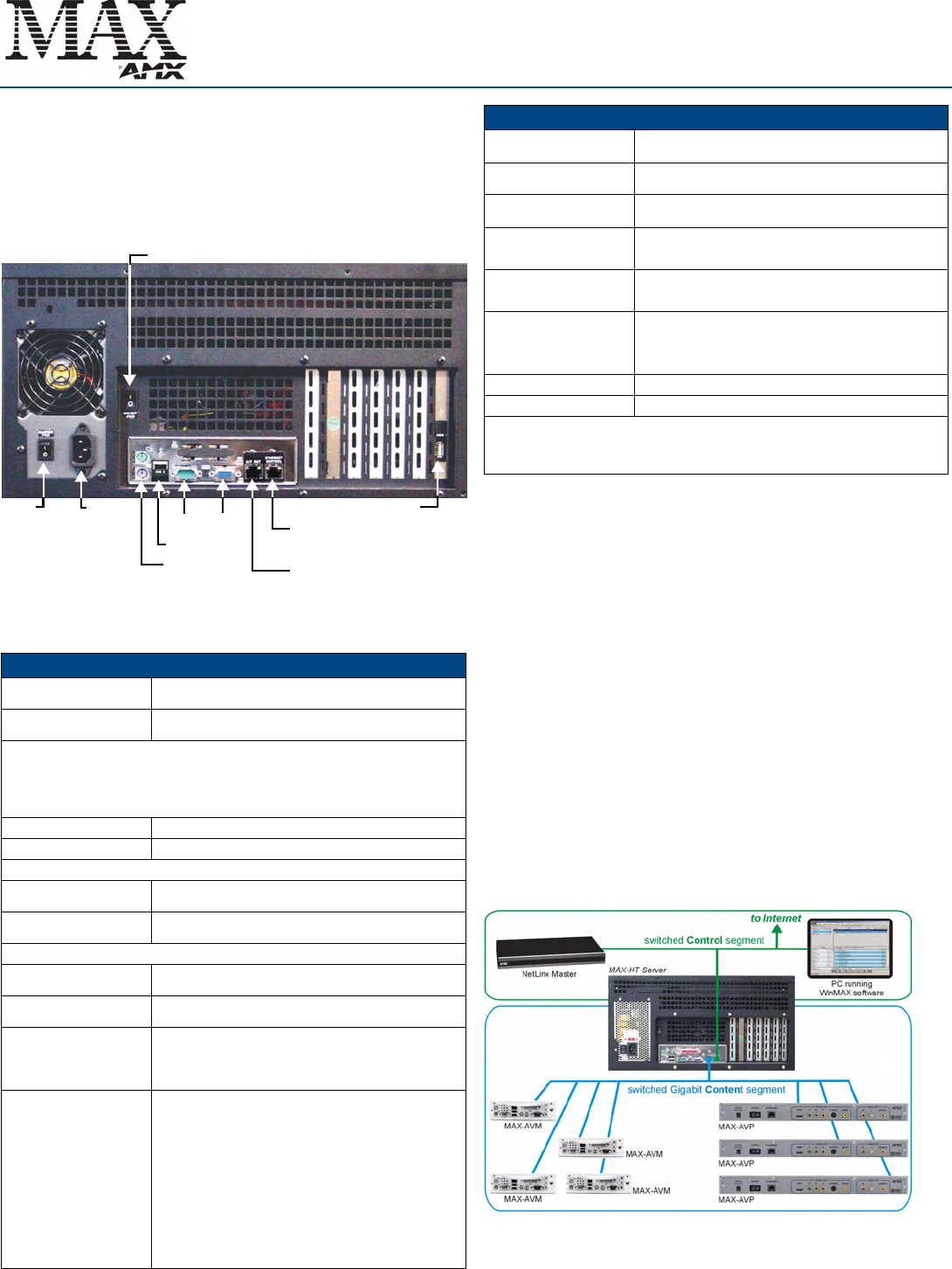
Network Segment Layout for MAX-HT Servers
It is required that the control (ETHERNET CONTROL) segment of the network is kept
separated from the (switched) content delivery (A/V OUT) segment, as indicated
below.
Note: Static electricity can damage electronic circuitry. Before touching the MAX-HT,
discharge any accumulated static electricity from your body by touching a grounded
metal object.
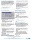
FIG. 1
MAX-HT04/HT12 Home Theater Servers (Rear Panel Components)
MAX-HT04/HT12 Specifications
Device Models: • MAX-HT04 (FG 2178-14)
• MAX-HT12 (FG 2178-15)
Storage Capacity: • MAX-HT04: 1.1 TBs, 275 DVDs (max) / 138 DVDs (min.)
• MAX-HT12: 4.0 TBs, 1000 DVDs (max) / 500 DVDs (min.)
Notes:
• The MAX number of DVDs is based on DVDs at 4.0 GB.
• The MIN number is based on the largest DVD at 8.0 GB.
• DVD capacity is based on typical commercial DVDs.
• DVD size is based on total DVD image, not the length of the movie.
The actual server capacity will vary depending on specific mix of DVDs and CDs in the library,
Disc Management RAID 5 disc drive system
Power: 110-240 VAC +/- 10%, 50/60Hz
AC Current Draw - MAX-HT04:
120 VAC: • Bootup/Power Cycle Peak - 3.0A @ 120V = 360 watts
• Normal Usage Peak - 1.9A @ 120V = 228 watts
240 VAC: • Bootup/Power Cycle Peak - 1.5A @ 240V = 360 watts
• Normal Usage Peak - 0.95A @ 240V = 228 watts
AC Current Draw - MAX-HT12:
120 VAC: • Bootup/Power Cycle Peak - 6.0A @ 120V = 720 watts
• Normal Usage Peak - 3.0A @ 120V = 360 watts
240 VAC: • Bootup/Power Cycle Peak - 3.0A @ 240V = 720 watts
• Normal Usage Peak - 1.5A @ 240V = 360 watts
Front Panel Components:
(remove Faceplate to access)
• MAX-HT04: 4 hot-swappable 400GB hard drives
• MAX-HT12: 12 hot-swappable 400GB hard drives
• DVD/CDRW drive
• Drive Status LEDs
• Ventilated front cover
Rear Panel Components: • Power Cable connector: IEC connector for AC power cable
(included)
• Master Power Supply switch: Turns the power supply on/off
• Power On/Off toggle switch: Turns the MAX-HT on/off
• PS/2 Keyboard and Mouse ports (for diagnostics only)
• USB ports 1 & 2: Type A USB connectors connect to MAX-AOM
module(s) for audio distribution
• RS-232 port: (for diagnostics only)
• VGA port: (for diagnostics only)
• ETHERNET CONTROL port: RJ-45 Gigabit Ethernet port
provides 1000/100/10 Mb/s network connectivity between the
MAX-HT and the NetLinx Master or PC
• A/V OUT port: RJ-45 Gigabit Ethernet port provides
1000/100/10 Mb/s network connectivity between the MAX-HT
and MAX-AVP Audio-Video Players and/or MAX-AVM
module(s) for A/V distribution
Power
PS/2 keyboard
RS-232 VGA
USB 1 port
A/V OUT
USB 2 port
Master
ETHERNET CONTROL
switched Control segment
(to NetLinx Master or PC)
switched GB Content segment
(to MAX-AVPs and/or MAX-AVMs)
& mouse ports
Power
switch
cable
connector
Power ON/OFF toggle switch
MAX-HT04/HT12 Specifications (Cont.)
Dimensions (HWD):
(without rack ears)
• 8.75" x 16.95" x 18.90" (22.23 cm x 43.50 cm x 48.00 cm)
• 5 RU (mounts in a standard 19” equipment rack)
Weight (servers only): • MAX-HT04: 60 lbs (27.22 kg)
• MAX-HT12: 68 lbs (30.84 kg)
Shipping Weight (including
mounting equipment and box)
• MAX-HT04: 83.9 lbs (38.06 kg)
• MAX-HT12: 91.9 lbs (41.69 kg)
Operating Environment: • Operating Temperature: 10º to 35º C
• Operating Relative Humidity: 20% to 80% (non-condensing)
• Minimum Ventilation Clearance: 3" front and 3" rear
Included Accessories: • One 6’ (1.83m) power cable
• One DVD, one CD
• Rack-Mounting Kit/Installation Guide
Other AMX/MAX Equipment: • MAX-AVP Audio-Video Player (FG 2178-51)
• MAX-AVM Audio-Video Module (FG 2178-50)
• MAX-AOM Audio-Only (USB) Module (FG 2178-55)
• MAX-AOM-EX Expansion Kit (FG 2178-56)
• MAX-MDL200 Multi-Disc Loader (FG 2179-01)
Certifications: UL Listed E252362, FCC, CE
Required Firmware version: 4.30.23 or greater - contact AMX Technical Support for details
Notice: MAX Products are not designed or intended to, and may not be used to, violate anyone’s
copyright or other intellectual property rights. Each user of the MAX Products may only use the
Products in connection with materials legally owned or licensed by such user and only to the extent
such ownership or license rights permit such use.
FIG. 2 Network Segment Layout