


5. Cabling of an ILite display
5.1 ILite tile connectivity
Connectivity
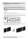
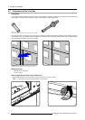
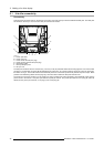
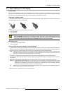
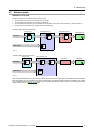
There are three connection ports on the back of an ILite tile. One power input port and two bidirectional data ports. The data ports
are located on the re-sync unit, which can easily be removed from the tile.
A
F
F
G
B
D
E
C
E
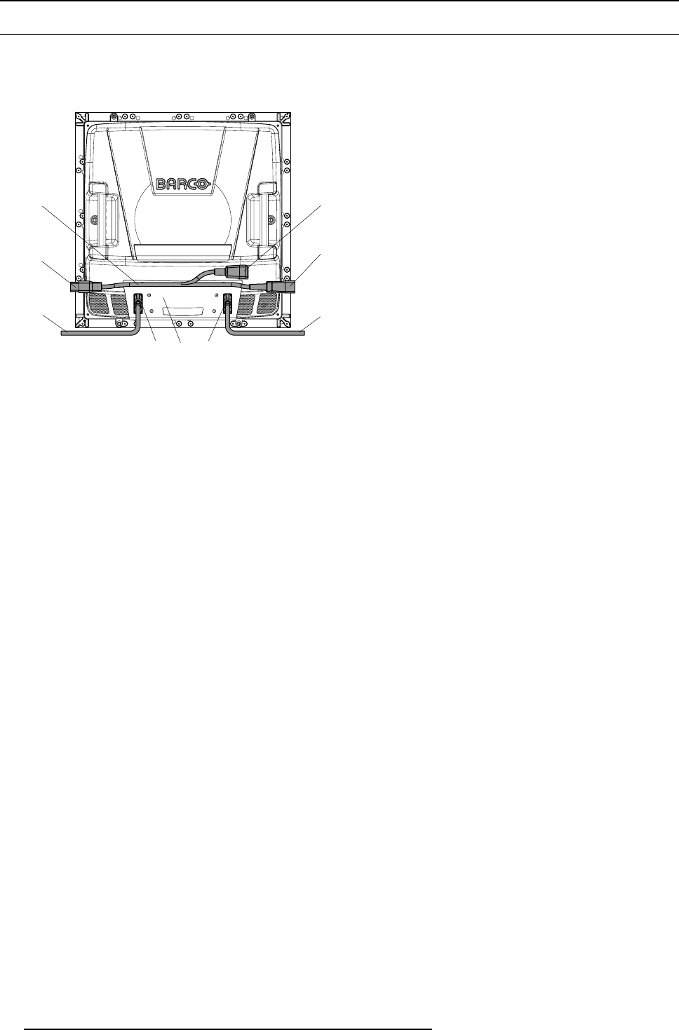
Image 5-1
A Power split cable.
B Power input port.
C Power link to next tile (C19 plug).
D Power link from previous tile (C20 plug).
E Data linking cable.
F Data input/output ports.
G Re-sync unit.
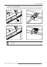
The data ports consist of two DVI connectors (F). T
he re-sync unit (G) automatic detects the incoming signal on one of the two DVI
connectors. The other DVI connector will automatically act as output port. So, it doesn’t matter on which DVI connector, left or right,
the data is coming in. The ILite tile switches the functionality of the DVI connectors spontaneously between input and output. Barco
provides short data linking cables with DVI p
lugs (E), which are used to realize the data path from tile to tile.
The power input connector consist of a C14 socket type. Barco provides ILite power split cables, which subdivide power from the
power source to the ILite tile. One power split cable is required per ILite tile. The power split cable has a C13 plug (B), which fits
directly into the power port of the tile, a C19 plug (C) and a C20 plug (D).
38
R5976522 FIXED ILITE DISPLAY 17/11/2006