T1 Definitions
3-3
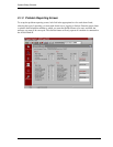
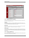
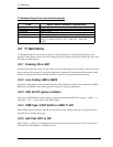
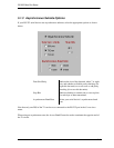
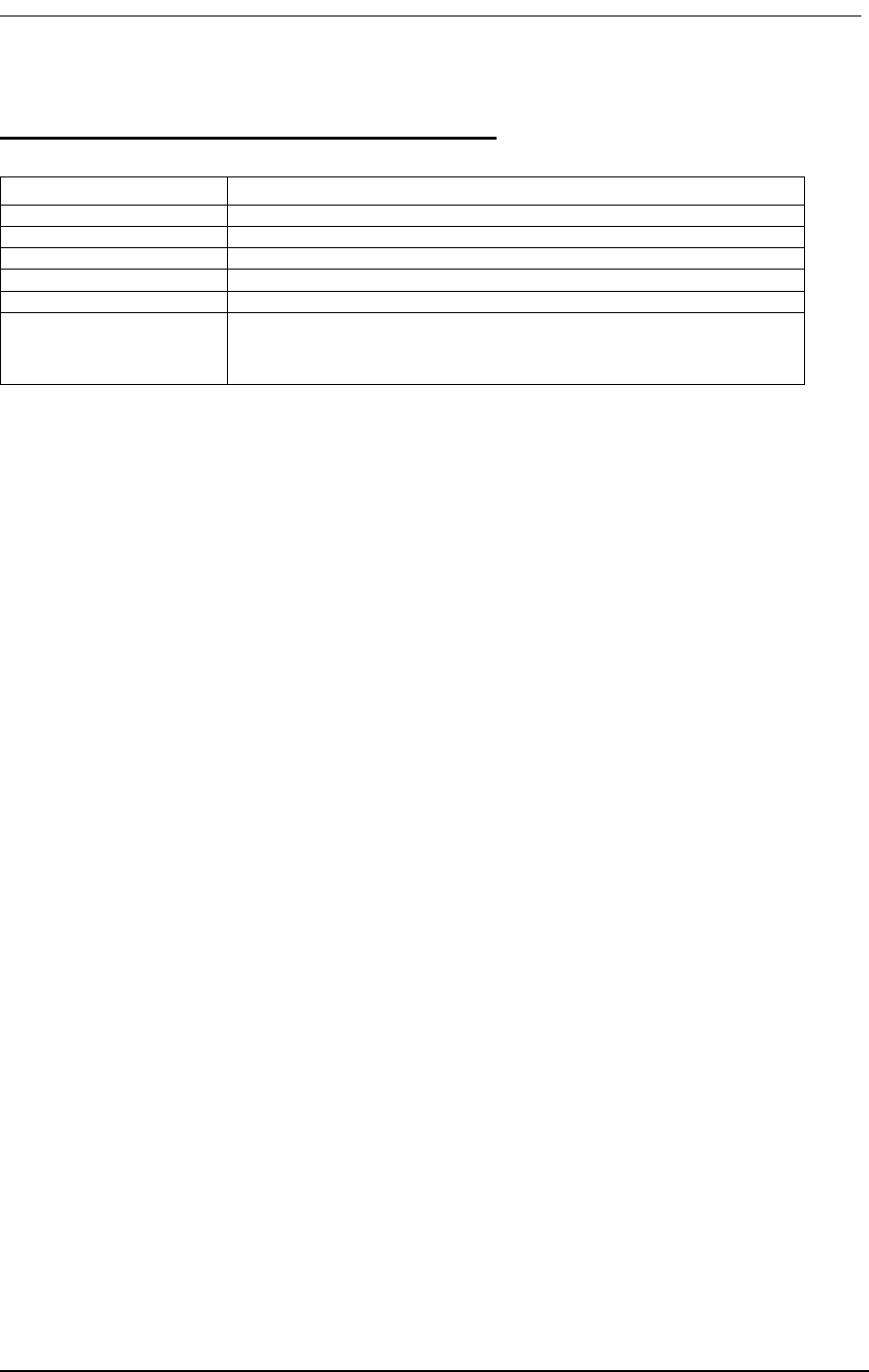
T1 Hardware Setup Fields (see definitions below)
3.2 T1 Definitions
T1 Hardware Setup fields are used to set up the T1 network interfaces to match the characteristics of the
attached T1 data streams, such as line code, framing format, and enabling detection of inband CSU loop codes.
The fields are defined below.
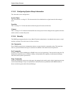
3.2.1 Framing: D4 or ESF
Selecting D4 sets the basic frame structure to the 12 frame D4 Superframe format. If ESF is selected, the basic
frame structure of the attached T1 span line should be the 24 frame ESF Extended Superframe format, which
includes a 4 Kbps Facility Data Link (FDL) channel for supervisory and performance monitoring.
3.2.2 Line Coding: AMI or B8ZS
Set the line coding either to Alternate Mark Inversion (AMI) (Default) or Binary 8 Zero Substitution (B8ZS).
B8ZS allows for 64Kbps clear channel operation, required for most data applications.
3.2.3 CSU On/Off: Ignore or Detect
Causes the ACCESS Bank II to either ignore or respond to the inband D4/ESF CSU loop up (…00001…) or
loop down (…001…) codes. Detect is the default setting.
3.2.4 PRM Type: AT&T 54016 or ANSI T1.403
Detect AT&T 54016 or ANSI T1.403 ESF out-of-band loop codes with the exact loop code type detected as
specified above, and FDL Messaging.
3.2.5 Self Test: OFF or ON
Place T1 Span 1 or Span 2 in an internal loopback configuration and perform system self test, and provide to
FSX channels either ringback or a 1000 Hz test tone.
Field Input Choices (defaults in parentheses)
Framing D4, (ESF)
Line Coding (B8ZS), AMI
CSU On/Off (Detect), Ignore
PRM Type (AT&T 54016), ANSI T1.403
Self Test (Off), Ringback, Test Tone
Line Build Out CSU (0dB/DSX [0’-133’]), DSX [133’-266’], DSX [266’-399-], DSX
[399-‘533’], DSX [533’-655’], CSU- 7.5dB, CSU - 15dB, CSU -
22.5dB


