


Chapter 14. Event Section In-Depth
6. EXTENDED GUI
Page
145
6. EXTENDED GUI
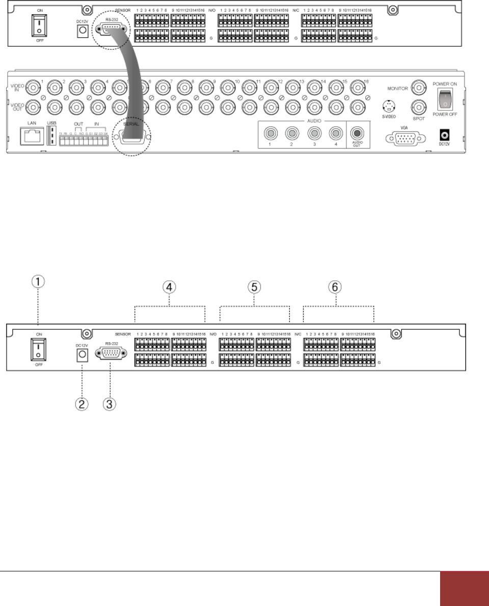
Once the extended box is connected, up to 16 sensor inputs and alarm outputs can be usable.
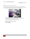
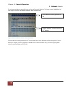
▶ Connection diagram
Connect “Serial” port of DVR with “RS-232” port of the extension box.
Connect the power cable of extension box and then turn the power on.
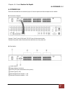
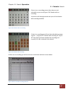
▶ Description
① Power switch
② Power adaptor connector
③ RS-232 port (Port connected to the system)
④ Sensor input (1~16)
⑤ Normal Open alarm output : 1~16
⑥ Normal Close alarm output : 1~16