


Chapter 2. Hardware Description
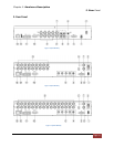
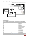
3. Rear Port Specification and Connection Examples
Page 27
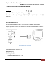
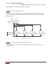
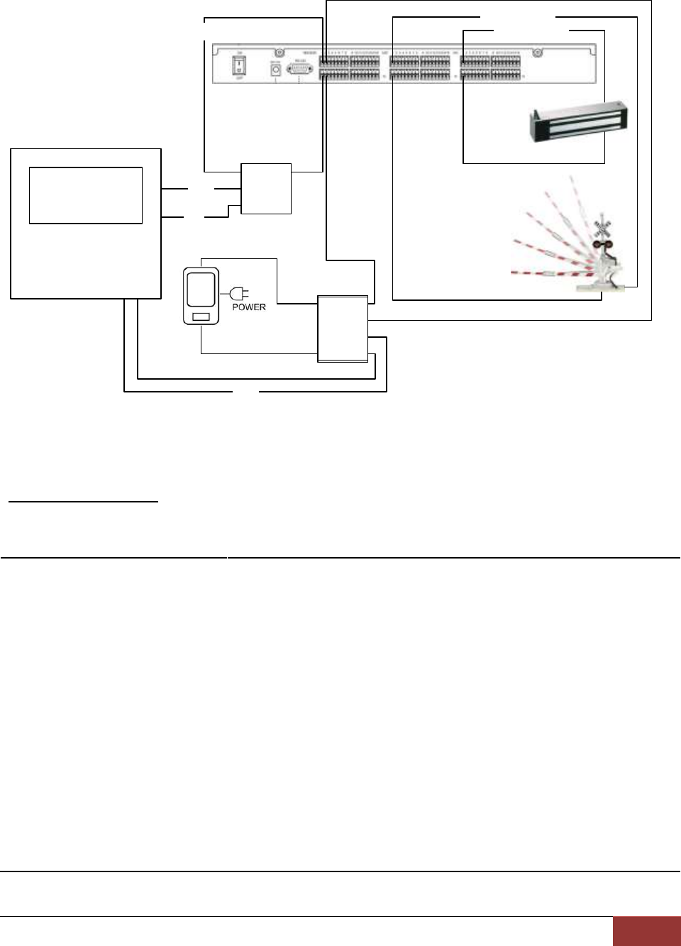
Sensor 2
V
+
V
out
C
+
GND
C
-
Relay Switch
C
B
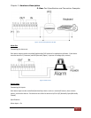
Alarm Panel
V
in1
V
in2
V
out1
V
out1
V
out2
V
out2
Relay Switch
12V DC
PGM1
+5V
Arm or Dis-Arm information
NC output Dry Contact
NO output Dry Contact
+3V DC
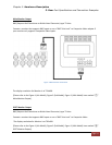
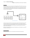
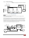
Figure 12 Alarm Sensor Extension Box Wire Example
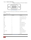
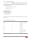
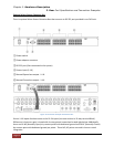
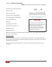
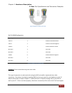
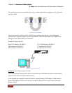
10-Way Terminal Block
There are RS-485, Alarm Output, and Sensor Input (1 to 4 Sensor) all located in 10-Way Terminal Block.
Signal Type
Pin Number
Description
Tx
1
RS-485 Transmit
Rx
2
RS-485 Receive
G
3
Ground (RS-485)
C
4
Common (Ground for Alarm Out)
NO
5
Normally Open (Alarm Out)
G
6
Ground (Sensor)
S1
7
sensor connection port 1
S2
8
sensor connection port 2
S3
S4
9
10
sensor connection port 3
sensor connection port 4
Table 13. 10-Way terminal block pin-out