


Stand
Large screw
Philips
PHDVD5, PH5DSS,
PMDVR8, PDVR8
115
DirectTV
RC23
10463
RCA
RCU807
135
One for All
URC-6690
0464
Sony
RM-VL600
8043
Comcast
M1057
0463
Dish Network
VIP508, VIP622
720
Motorola
DRC800
0463
TIVO
Series 3, HD
0091
Universal remote control makers and models Set-top box makers and models
Universal remote control TV codes (for all Dynex TVs manufactured after Jan. 1, 2007)
Stand column
Smaller screws (3)
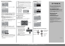
Connecting a DVD or Blu-ray DVD player, cable
box, satellite receiver or game station
Using HDMI (best)
Using component (better)
Note: Cable connectors and jacks are often color-coded. Match the colors when
you connect the AV cable.
Connecting an antenna
Connect a 75 ohm cable (not included) to the ANT/CABLE IN jack on the back of
your TV and the RF OUT jack on the antenna.
Connecting a VCR, camcorder, or game
(good)
Note: Cable connectors and jacks are often color-coded. Match the colors when
you connect the AV cable.
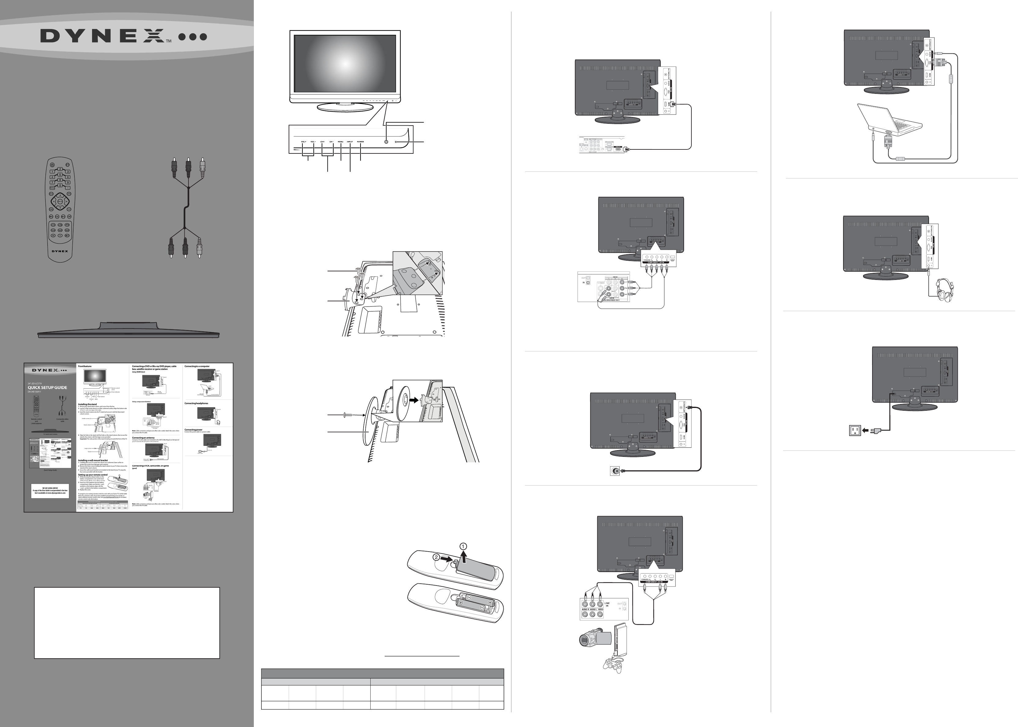
Connecting to a computer
Connecting headphones
Connecting power
Connect the power cable to a power outlet.
Front features
Installing the stand
1 Remove the stand, stand column, and screws from the box.
2 Lay the TV at (screen down) on a at, cushioned surface. Align the bottom side
of the TV with one edge of the table.
3 Insert the stand column into the TV stand and secure it with the three stand
column screws.
4 Align the holes in the stand with the holes on the stand column, then secure the
stand to the column with the larger screw provided.
Important: The wide portion of the stand should go towards the front of the TV.
Installing a wall-mount bracket
1 Carefully place your TV screen face-down on a cushioned, clean surface to
protect the screen from damages and scratches.
2 Remove the three screws holding the stand column to your TV, then remove the
stand and the stand column.
3 Secure the wall-mount bracket (not included) to the back of your TV using the
four screws provided with the bracket.
Setting up your remote control
1 While pressing the release button on the
battery compartment cover on the back
of the remote, lift the cover o the remote.
2 Insert two AAA batteries into the battery
compartment. Make sure that the + and -
symbols on the batteries align with the
+ and – symbols in the battery compartment.
3 Replace the cover.
To program your existing remote control to work with your Dynex TV, see the table
below for common codes. If you have problems programming your remote, or
need a dierent remote control code, visit www.dynexproducts.com for the latest
remote control code information.
24" LED-LCD TV
QUICK SETUP GUIDE
DX-24E150A11
Remote control
and
2 AAA batteries
Composite video
cable
TV stand and screws
Quick Setup Guide
Remote control
sensor
Power indicator
Power cord
Power outlet
HDMI cable
(not included)
HDMI device
Back of TV
Component video device
Back of TV
Component
video cable
Component audio cable
(not included)
75-Ohm coaxial cable
Back of TV
Antenna, cable TV,
or satellite RF jack
Back of TV
Back of VCR
AV cable
Back of camcorder
or game
Back of TV
D-Sub cable (analog RGB)
Computer
Audio cable
(stereo mini plugs)
Back of TV
Volume
+/-
Menu
Channel
+/-
Power button
Input
WE ARE GOING GREEN!
A copy of the User Guide is not provided in the box
but is available at www.dynexproducts.com