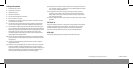
DX-AD113 UHF/VHF/FM Amplier
Features
• Amplies 50-900 MHz signals
• Low signal noise
• Flat frequency response
• Ultra stable circuit
• High sensitivity to ensure picture stability and clarity
• Easy installation, including screw brackets for stable wall mounting
• For indoor use only
Package contents
• UHF/VHF/FM amplier
• Screws (2)
• Quick Setup Guide
Specications
Setting up your amplier
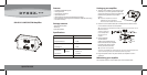
1 To attach the amplier to a wall, drill two pilot
holes 4.53 in. (115 mm) apart and install wall
anchors (if mounting to a brick or hollow wall)
before securing with the two provided
screws.
Tip: Attach the amplier to the wall or
baseboard as close as possible to
where the antenna cable enters the house.
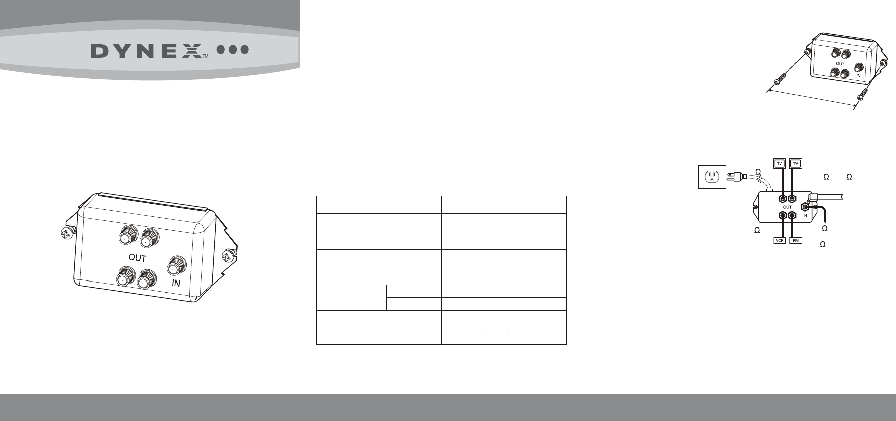
2 Attach a 75-ohm coaxial cable (not included) from the cable TV outlet
or TV to the IN connector on the amplier.
Tip: If your antenna is equipped with a 300-ohm at wire, you can attach it to an
female 75/300-ohm
matching transformer
(not included) before
connecting to the
amplier.
3 Attach additional
75-ohm coaxial
cables (not included) from the
OUT connectors on the amplier
to the RF inputs of each video
device you want to connect.
Tip: If you are not using all four
outputs on the amplier, we recommend that you cap the unused outputs with a
75-ohm terminating resistor (not included) to prevent signal loss.
4 Plug the amplier into an AC power outlet. Your amplier is now in
operation.
Maintaining your amplier
Your amplier contains no serviceable parts. Do not disassemble.
QUICK SETUP GUIDE
Bandwidth
Gain
Response atness
Maximum output (IMA 60 dB)
Noise gure
Impedance
Connectors
Power requirement
Input
Output
50-900 MHz
4.5 dB
±2 dB
86 dBμV
5.5 dB
75 ohm x 1
75 ohm x 4
“F” female
120V ~ 60 Hz 0.02A 2.4W
4.53 in. (115 mm)
75 cable
or
300 at wire
75 cable
75 cable
75 /300
matching transformer