MCP 1000 • Installation
Installation, cont’d
2-6
MCP 1000 • Installation
2-7
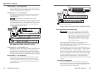
Cables must be made with the appropriate connector on each
end. Regardless of the connector that is being used, the wiring
must be one-to-one (for example, red-to-red and A-to-A).
CAUTION
Damage may occur to circuits if cable wire
assignments are not the same on both ends.
The total cable length for connecting MCP 1000s and
MKP 1000s to a matrix system must not exceed 1000 feet
(305 meters).
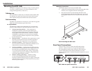
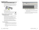
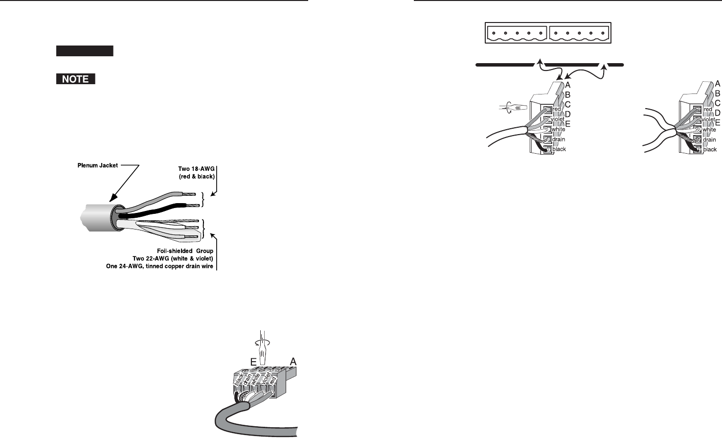
To attach connectors to the cables,
1. Trim approximately 1.5 inches of the cable jacket to expose
the four insulated wires and a bare drain (ground) wire
(silver colored).
Trimming the cable jacket
2. Cut off and discard the foil shield.
3. Strip 0.25 inches of insulation from each of the four wires.
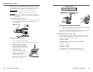
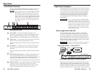
4. Twist the strands of the black
wire, insert it into the opening
that corresponds to pin E, and
tighten its captive screw. (See the
illustration at right.)
5. Twist the strand of the drain
wire, insert it into position D, and
tighten its captive screw.
6. Connect the remaining wires in
the same way (for this example,
white, violet, and red).
ED
COMM-LINK PORT
CBA EDCBA
5 mm captive
screw connector
Wiring the 5 mm captive screw plugs
7. Choose the appropriate captive screw connector and repeat
steps 1 through 6 for each cable end.
Both types of captive screw connectors use a “moving cage” to
damp the wires, without the need for soldering.
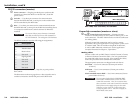
Extron’s Plenum Comm-Link cable
Extron’s Plenum Comm-Link cable was designed for use with
the MCP 1000 and MKP 1000. If another cable will be used, it
must meet the following specifi cations:
A (red) — 18 AWG
B (violet or blue) — 22 AWG (grouped and shielded)
C (white) — 22 AWG
D (drain) — 24 AWG
E (black) — 18 AWG
See appendix A, "Specifi cations, Part Numbers, and
Accessories," for a list of Extron cable part numbers.
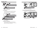
1
3.5 mm captive
screw connector on
MCP 1000


