RM 700M Mounting Kit Installation Guide
Extron USA - West
Headquarters
+800.633.9876
Inside USA / Canada Only
+1.714.491.1500
+1.714.491.1517 FAX
Extron USA - East
+800.633.9876
Inside USA / Canada Only
+1.919.863.1794
+1.919.863.1797 FAX
Extron Europe
+800.3987.6673
Inside Europe Only
+31.33.453.4040
+31.33.453.4050 FAX
Extron Asia
+800.7339.8766
Inside Asia Only
+65.6383.4400
+65.6383.4664 FAX
Extron Japan
+81.3.3511.7655
+81.3.3511.7656 FAX
Extron China
+400.883.1568
Inside China Only
+86.21.3760.1568
+86.21.3760.1566 FAX
Extron Middle East
+971.4.2991800
+971.4.2991880 FAX
© 2009 Extron Electronics. All rights reserved.
Overview
The Extron
®
RM 700M allows the TLP 700MV TouchLink
™
panel to
be mounted in a standard rack. The RM 700M uses 5 U of vertical
space in a standard 19 inch equipment rack.
This guide provides basic instructions for an experienced installer
to mount and connect the TLP 700MV.
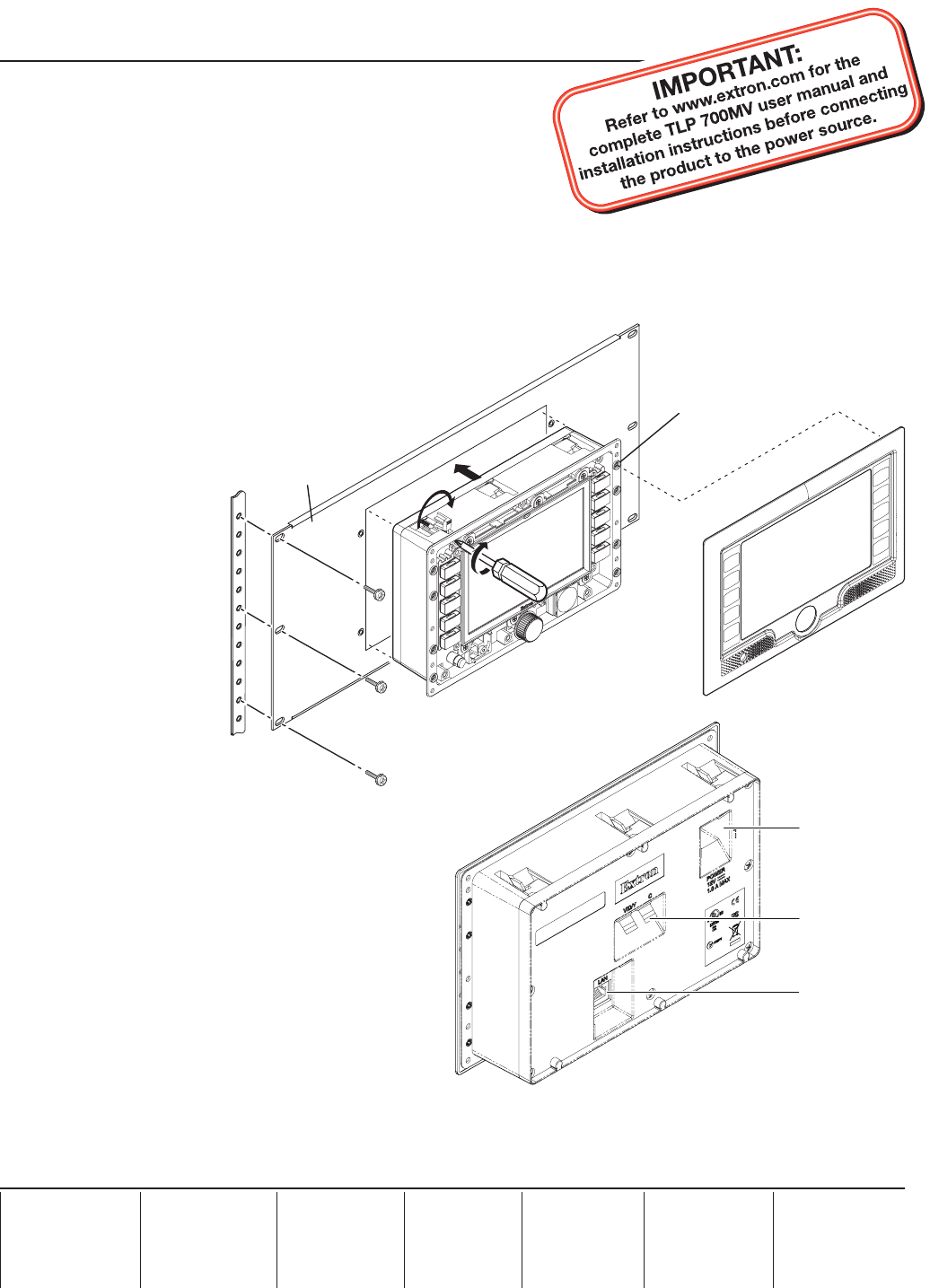
Using the RM 700M mounting kit
To mount the TLP 700MV in any standard 19" equipment rack, follow these instructions:
1.
Disconnect all cables from the TLP 700MV.
2. Run cables for video, network and power to the rack.
3. Secure the RM 700M to the rack, using
the screws provided by the rack's
manufacturer.
4.
Remove the faceplate from the
TLP 700MV and ensure
that all the locking
arms are laying
flush with the unit.
5.
Push the
TLP 700MV
through the hole
in the mounting
kit and tighten the
six screws for the
locking arm. As
the screws tighten,
the locking arms
rotate and clamp
against the back
of the mounting
kit, holding the
TLP 700MV in place.
6. Connect the cables to the rear panel connectors.
Connect the LAN port to the network with a
straight-through cable.
Connect an S-video or composite video source to
the unit, using these two BNC connectors:
For S-video, connect the Y (luminance) signal •
to the VID/Y input and the C (chrominance)
signal to the C input.
For composite video, connect the input to the •
VID/Y input.
Connect the power input to a 12 VDC, 1.0 A
power supply, using the 2-pole captive screw
connector.
7. If you do not plan to calibrate the TLP 700MV immediately (see the TLP 700MV user's manual), replace the
faceplate by pressing the catches on the faceplate into the corresponding holes on the sides of the panel.
68-1793-01
Rev. A 08 09
Tighten screws to
rotate locking arms.
Secure RM 700M to rack.
Screws (6) Provided
by Manufacturer
Faceplate snaps to unit.
(4 plcs ea side)
RM 700M
Power input
Video inputs (2)
LAN input
TLP 700MV Rear Panel


