


12-64B, 8-66B Installation, Operation and
Troubleshooting Guide
Document 06EN003322 Rev. -
Step 1. Pre-Installation
A. To get the best results, the sensor should be mounted 20 pipe diameters downstream from any flow disturbance
(valve, pipe elbow) and 10 pipe diameters upstream from any disturbance.
24 Hour Factory Service Hot Line: 1 (800) 854-1993
B. Verify the serial numbers on the enclosures, flow element and electronics (control circuit) match. The instrument
may not work if the serial numbers do not match.
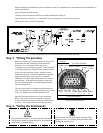
Tag Location
On the top side of the local enclosure
The instrument tag shows the model number, tag number (if
noted on the order) and serial number along with other
important safety information. Compare this information with the
appropriate pipe installation drawings to be sure the instrument
is the correct configuration. Match the tag serial number on the
enclosure, flow element and control circuit.
Electronics Serial Number
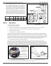
Step 2. Flow Element Installation
Alert: DO NOT change the orientation of the flow element in the enclosure as the interconnecting RTD and
heater wiring could be stressed and damaged. DO NOT apply any torque to the flow element
enclosure - only apply to the pipe surface itself.
Install the flow element, with the Flat Up and Level (shown above) or parallel to the flow media (±2°) for top mounted
instruments. The enclosure, flow element and electronic control circuit card serial numbers should all match.
Flow Element Serial Number.
Also Showing Sensor Orientation Flat.
(Located near the enclosure.
It is also on the enclosure tag.)
C. Recommended installation/troubleshooting tools are a 1-3/8 inch open ended wrench to fit the NPT connection, a
small flat blade screw driver for manipulating potentiometers, a medium flat blade screwdriver for tightening
connections, 3 mm allen wrench for CENELEC approved instruments, and a DVM for Ohm/Voltage
measurements.