M2488 PRODUCT GUIDE MAINTENANCE AND SERVICING
April 1997 CG00000-011503 REV. A 8-55
8-11.13 WTL PCBA Remove and Replace Procedures
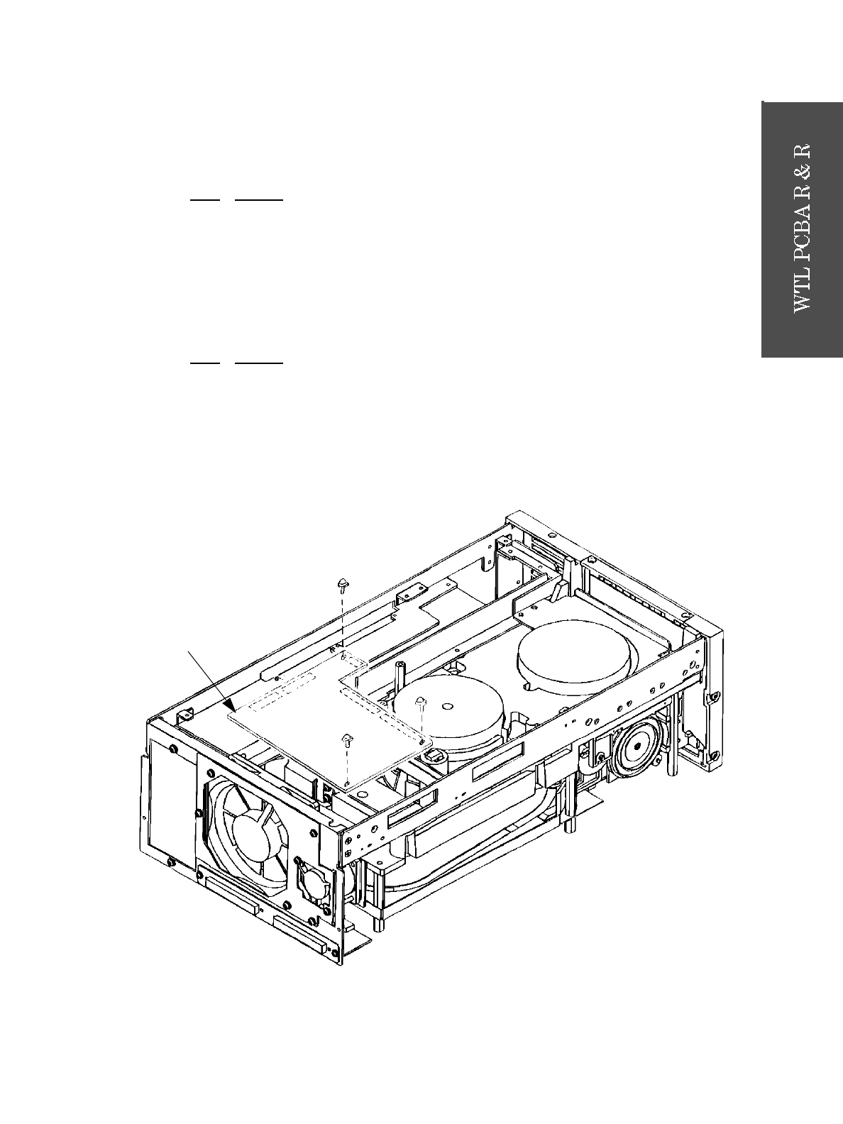
Refer to Figure 8-13 for location of the WTL PCBA.
8-11.13.1 WTL PCBA Removal
8-11.13.2 WTL PCBA Replacement
Figure 8-13. WTL PCBA
STEP ACTION
1 Perform the RDL PCBA removal procedure in paragraph 8-11.12.1 on page 8-54.
2 Remove the three screws securing the WTL.
3 Disconnect connectors CNJ30 and CNJ31.
4 Remove the WTL PCBA.
STEP
ACTION
1 Insert the WTL PCBA into the bottom of the drive.
2 Connect connectors CNJ30 and CNJ31.
3 Align screws holes, then insert three screws and tighten.
4 Perform the RDL PCBA replacement procedure in paragraph 8-11.12.2 on page 8-54.
WTL


