42
CHAPTER 3 OPERATING THE EMULATOR
3.6 User Data Bus Switching
Set the setting of the user data bus selection switch.
■ Switching of the user data bus
If probing target pins (P00 to P07 and P10 to P17) have special specifications, such as for high-
voltage ports, the user data bus probing circuit must be set to the disconnected status.
When the external bus of the evaluation MCU is not used, the disconnected status is the
recommended setting for the user data bus probing circuit.
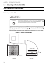
Using the user data bus selection switch on the emulator, set the user data bus probing circuit
to the connected or disconnected status.
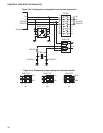
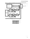
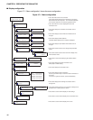
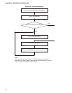
Figure 3.6-1 "Configuration of the peripheral circuit for the user data bus selection switch"
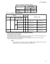
shows the configuration of the peripheral circuit for the user data bus selection switch. Table
3.6-1 "Settings of user data bus selection switch" lists switch settings.
Note:
This circuit has a function equivalent to that of a pull-up circuit with high resistance.
If all buses in the evaluation MCU and user system are in the Hi-Z state, about 3.0 V
appears on the user data bus.
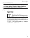
Make sure that power to the product is turned off and the power plug is
disconnected from outlets before handling switches. Doing so may
result in device problems or electric shock.
CAUTION
Prohibition
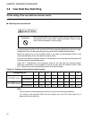
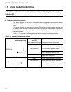
Table 3.6-1 Settings of user data bus selection switch
Probing target pin 12345678
P00 to P07
(P0 SENSE setting)
Connected ON ON ON ON ON ON ON ON
Disconnected OFF OFF OFF OFF OFF OFF OFF OFF
P10 to P17
(P1 SENSE setting)
Connected ON ON ON ON ON ON ON ON
Disconnected OFF OFF OFF OFF OFF OFF OFF OFF


