E-10
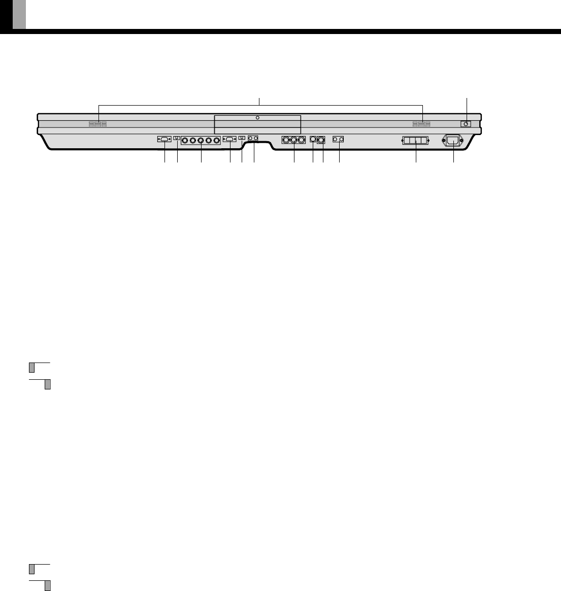
1 Main power switch
Press this switch when the power is OFF to turn it ON. When you do so, the power indicator lamp will become red, indicating that
you can turn ON or OFF the power to the display using either the remote control or the display’s control panel.
Press this switch when the power is ON to turn it OFF.
2 RS-232C terminal (RS-232C)
This terminal is provided for you to control the display from the PC. Connect it to the RS-232C terminal on the PC.
When connecting a cable, attach a ferrite core to the cable. (PDS4213W-H only) (See P. E-14.)
* No RS-232C cable is supplied with the display. The type of cable to be used varies depending on the PC model. Contact your
dealer for more information.
3 RGB2 synchronization switch (SYNC SW2 TTL/ANALOG (75 Ω))
This switch is used to terminate the RGB2 terminal with 75 Ω for receiving horizontal (H) and vertical (V) synchronization signals.
TTL: Used when sending RGB signals from the PC to the RGB2 terminal
ANALOG (75 Ω): Used when sending analog synchronization signals to the RGB2 terminal
4 RGB2 input terminal (RGB2 INPUT/BNC x 5)
Connect this terminal to the PC’s display (analog RGB) output terminal.
* No RGB cable is supplied with the display. The type of cable to be used varies depending on the PC model. Contact your dealer
for more information.
5 RGB1 input terminal (RGB1 INPUT/mD-sub)
Connect this terminal to the PC’s display (analog RGB) output terminal.
* No RGB cable is supplied with the display. The type of cable to be used varies depending on the PC model. Contact your dealer
for more information.
6 RGB1 synchronization switch (SYNC SW1 TTL/ANALOG (75 Ω))
This switch is used to terminate pins 13 and 14 of the RGB1 terminal with 75 Ω respectively for receiving horizontal (H) and vertical
(V) synchronization signals.
TTL: Used when sending RGB signals from the PC to the RGB1 terminal
ANALOG (75 Ω): Used when sending analog synchronization signals to the RGB1 terminal
7 Sound1 input terminal (AUDIO 1 INPUT)
Connect this terminal to the sound output terminal of your VCR, etc.
8 Component video input terminal (COMPONENT VIDEO INPUT)
Connect this terminal to the component video output (color difference output) terminal of your HDTV unit or DVD player.
When connecting a cable, attach a ferrite core and wire clamper to the cable. (PDS4213W-H only) (See P. E-14.)
9 S-video input terminal (S-VIDEO INPUT)
Connect this terminal to the S-video output terminal of your VCR or video disk player.
PART NAMES AND FUNCTIONS (Continued)
Bottom
D
23 4 567 8 90 A B C
1


