


0150-0193C 11 Calibur DVMR
e
Triplex
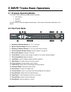
See section 3.11 for information about configuring the contacts as Normally Open or Normally Closed
in the menu system.
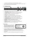
Normally Open, Zero Potential Relay Contact: Configure in menu as Normally Open.
Normally Closed, Zero Potential Relay Contact: Configure in menu as Normally Closed
TTL Active High: Configure in menu as Normally Closed.
TTL Active Low: Configure in menu as Normally Open.
Open Collector Active On: Configure in menu as Normally Open.
High: 5V (12V Tolerant)
Low: Ground
Inputs: 1 per channel.
Open Collector Active Off: Configure in menu as Normally Closed.
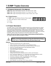
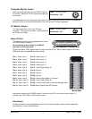
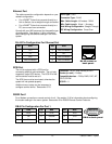
pin 16
pins 18
-
20
Alarm Input No. 2 - 15
pins 2-15
Alarm Input No. 1
Normally Closed
(Opens During Alarm)
DVMRe Triplex DB25 Connector
Typical Alarm Device
Normally Open
(Closes During Alarm)
Typical Alarm Device
pin 1
Alarm Input No. 16
Ground
Typical wiring for Alarm #1 as Normally
Open and Alarm #16 as Normally Closed.
Refer to each alarm device's manual for specific wiring details.
Normally Open and Normally Closed Connections
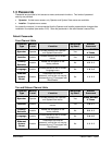
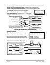
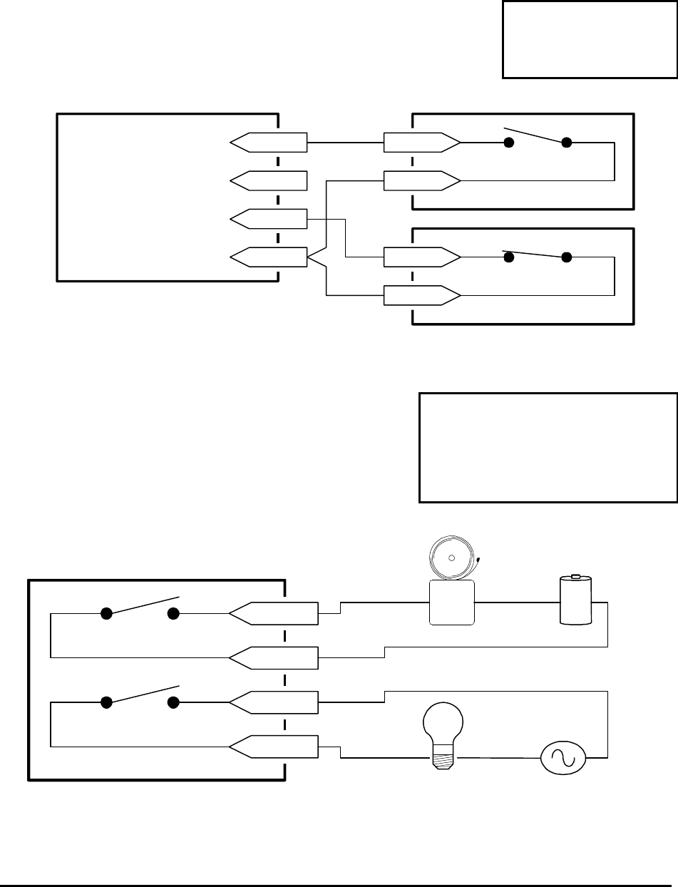
Alarm Relay Output
Output: Zero potential relay contacts,
programmable in menu system as
Normally Open or Normally Closed.
Voltage: 30V (Max)
Current: 500mA (Max)
The alarm relay output is activated when an alarm condition
exists. The alarm output is only active for the duration of the
alarm.
Alarm relays can be programmed in the menu system to
respond to macros, and video loss. See section 3.11 for
information about configuring the alarms in the menu system.
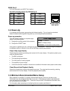
pin 22
pin 25
Output Relay No. 2
pin 17
pin 21
Output Relay No. 1
DVMRe Triplex DB25 Connector
Power
Source
Alarm
Device
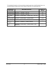
Typical wiring for Alarm Relays. Relays may be
programmed Normally Open or Normally Closed.
Power
Source
Controlled
Device