


Hardware Installation BusSecure User Manual
10 0150-0263A / May 2003
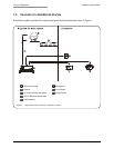
2.4 INSTALLING CAMERA ASSEMBLIES
The BusSecure system will support up to four cameras (color and/or monochrome). Cameras supported
by the BusSecure system can provide a 1.0 V pk-pk composite analog video signal, either NTSC or PAL,
at 75 ohm (CCTV standard).
2.4.1 INSTALLING SURFACE-MOUNT CAMERA ASSEMBLIES
Surface-mount camera housings are typically mounted to the ceiling, but can be mounted to any flat
vehicle surface.
Note: In some installations, it is necessary to use a metal tapping plate behind the mounting surface. If a tapping plate is used,
prepare it in the same way as the mounting surface (i.e., drill a cable entry hole and mounting holes in the appropriate locations).
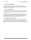
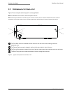
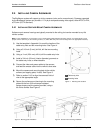
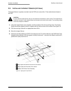
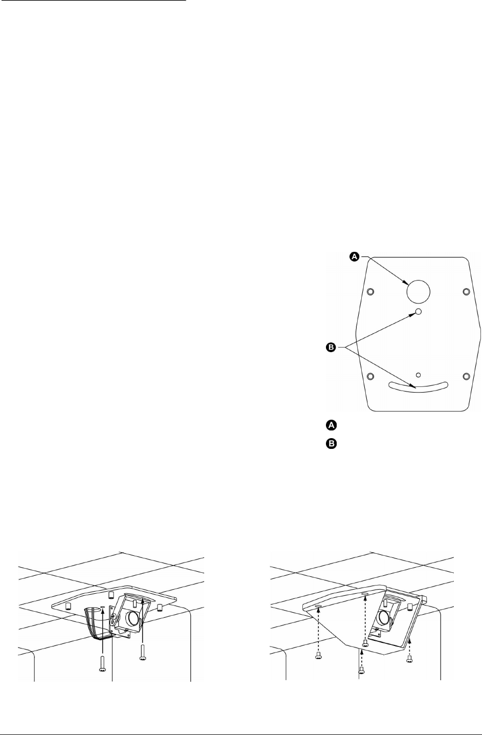
1) Use the template in Appendix A to mark the location of the
cable-entry hole and two mounting holes. See Figure 4.
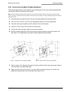
2) Using a 3/16-inch (5 mm) (drill bit, drill the two mounting
holes.
3) Using a 1-inch (25.4 mm) drill bit, drill the cable entry hole.
4) Install a 3/4-inch (20 mm) (interior diameter) grommet on
the cable entry hole, or where feasible.
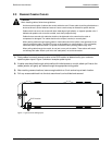
5) Connect the video and power cables to the camera,
and feed the excess cable into the vehicle’s duct area.
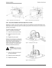
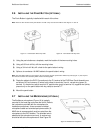
6) Mount the camera and mounting plate to the vehicle
surface (and tapping plate, if used). See Figure 5.
7) Refer to section 2.4.3 to align the camera’s field of
view to the appropriate angle.
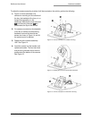
8) Secure the surface-mount housing to the mounting
plate with the four 3/8-inch tamper-resistant
tamper-torque machine screws provided, using a
bit of blue locktite. See Figure 6.
Cable entry hole
Mounting holes
Figure 4. Mounting hole locations
Figure 5. Mounting plate installation
Figure 6. Surface-mount housing installation