


TroubleShooting BusSecure User Manual
30 0150-0263A / May 2003
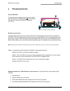
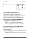
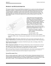
REMOVABLE DVR: LEDS FROM LEFT TO RIGHT
: Processor is writing to the hard drive (flashing
green).
: 12-V power supply present (solid green).
BUSSECURE UNIT DOES NOT START UP WITH VEHICLE IGNITION
To test input voltage: remove the 4-pin Molex connector from the connection box of the DVR. Verify that
when the ignition is off, the only voltage present is 12 VDC continuous (pin #1).
Verify that when the engine is started, there is 12 VDC continuous (pin 1) and 12 VDC vehicle running
voltages are present (pin 4). The DVR will not start without both power sources.
Visually verify that the pins of the 4-pin Molex connector are properly crimped and inserted in the
connector.
BUSSECURE UNIT STARTS UP BUT DOES NOT APPEAR TO BE CAPTURING IMAGES
LED LIGHTS AND ON THE FRONT OF THE DVR ARE NOT ALTERNATELY FLASHING
1) The DVR will not capture images if the key lock of the unit is open or unlocked. Close and lock the
door, then turn off the vehicle. After the vehicle has shut down, restart the engine.
2) Shortly after the DVR restarts, image capture can be verified by the green status light (or
combination of green and red status lights).
BUSSECURE OPERATING NORMALLY BUT STATUS LIGHTS ARE NOT ILLUMINATING
All status lights will be turned off after the DVR has shutdown completely.
The status lights are supplied with 12 VDC continuous power from the vehicle. Verity that continuous
voltage is present at the status light.
The ground for the status lights is supplied by the DVR connection box. To check the ground output with
a voltage meter, perform the following:
1) Place the positive meter probe onto an unused 12 VDC DVR output on the P1 or P2 terminal block
(see Figure 21).
2) Place the negative meter probe into terminal 13 of the P2 terminal block.
Figure 32. Front Panel LEDs