


2-4 IC697VAL348 8-Channel, 16-bit Digital-to-Analog Converter Board User’s Manual GFK-2059
– December 2001
2
Before Applying Power: Checklist
Before installing the board in a VMEbus system go through the following checklist to verify that
the board is ready for the intended operation:
1. Have the chapters on Theory and Programming of the DAC board, Chapters 3 and 4, been
read and applied to system requirements?
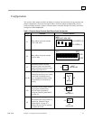
2. Review Table 2-1 on page 2-3 to verify the factory installed jumpers and board address
switches are set to what is desired.
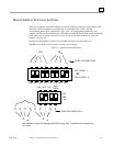
To change DAC board switches (S1 and S2) refer to “Board Address Selection Switches”
on page 2-5.
To change address modifier response jumper (JB) refer to “Address Modifier Response
Selection” on page 2-7.
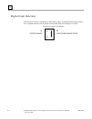
3. To change the DAC digital code selection refer to “Digital Code Selection” on page 2-8.
4. To use either the program controlled start convert mode or the external start convert mode
refer to “Program Controlled and External Start Convert Mode” on page 2-9.
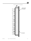
5. Has the cable, with proper mating connector, been connected to the analog output
connector (P3)? Refer to “Connector Descriptions” on page 2-10
.
Digital-to-Analog Converter Board Installation
After steps 1 through 5 have been reviewed, the DAC board may be installed in a VMEbus system.
(Do not install or remove the board with power ON). The DAC board may generally be installed in
any slot position, except slot "one" which is usually reserved for the master processing unit.