


GFK-2059 Chapter 2 Configuration and Installation 2-15
2
DAC Zero Offset and Gain Calibration
Note
This procedure assumes that the offset binary coding jumper (JA) is
selected.
1. Remove power from the Digital-to-Analog Converter Board.
2. Remove any cable connected to the P3 connector.
3. Remove the Digital-to-Analog Converter Board from the chassis assembly and install a
VMEbus Extender board in its place.
4. Install the Digital-to-Analog Converter Board onto the VMEbus Extender board.
5. Apply power to the module and allow 15 minutes for Temperature Stabilization before
making any measurements.
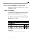
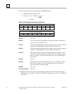
6. Using the IMMEDIATE UPDATE MODE write digital code 4100 HEX to the CSR
location XXXX0070. This HEX code is the Control Word for output to the Digital-to-
Analog Converter Board’s P3 connector.
7. Write 8000 HEX to each of the eight DAC channels at addresses XXXX0060 through
XXXX006E.
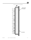
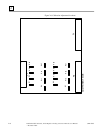
8. Using a 6-digit multimeter, monitor each DAC output at the P3 connector. Connect the
negative lead to connector P3 pin C2. Adjust each DAC's offset potentiometer for a
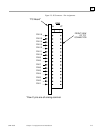
voltage of 0.0000 ±60 µV. Refer to Table 2-4 below and Figure 2-6 on page 2-16 for the
Potentiometer Location and P3 connector pin for each channel.
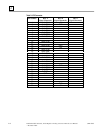
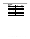
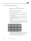
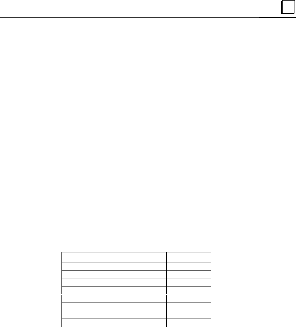
Table 2-4. Digital-to-Analog Converter Board Calibration Table
Channel Offest Pot Gain Pot P3 Connector
1 R23 R21 A2
2 R19 R17 A3
3 R31 R29 A4
4 R27 R25 A5
5 R3 R1 A6
6 R7 R5 A7
7 R15 R13 A8
8 R11 R9 A9
9. Repeat Step 7 using digital code FFFF HEX.
10. Using the multimeter, monitor each DAC output at the P3 connector. Connect the negative
lead to connector P3 pin C2. Adjust each DAC's gain potentiometer for a voltage of
9.99969 ±60 µV. Refer to Table 2-4 above and Figure 2-6 on page 2-16 for the
Potentiometer Location and P3 connector pin for each channel.
11. Remove extender and re-install board into the chassis. Calibration completed.