


4-2 IC697VAL348 8-Channel, 16-bit Digital-to-Analog Converter Board User’s Manual GFK-2059
– December 2001
4
Operational Overview
The Digital-to-Analog Converter Board performs digital-to-analog conversion on 16-bit positive
true offset binary or two’s complement coded words, with an analog output range of -10 to +10 V.
This provides for a resolution of 305 µV for each digital input of 1 LSB change. The buffered
output voltage settles to within 1/2 LSB in 10 µs.
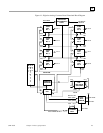
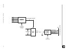
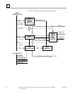
The DAC offers a Digital-to-Analog Integrated Circuit (IC) per channel. A Control and Status
Register (CSR) is loaded by the processor and this register controls the functioning of the board.
The processor can read the CSR at any time. The DAC board functional block diagram is shown in
Figure 4-1 on page 4-5. Double-buffered data latches precede each of the eight DACs. The data
latches allow versatility in the way that the DAC analog output may be updated.
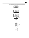
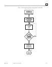
There are three methods by which new data can be converted by a DAC.
Each method is enabled/disabled by on-board jumpers and is further controlled by a CSR that must
be loaded by the user (the CSR contents are described in Tables 3-1 and 3-2 on page 3-2, Table 3-4
on page 3-4, and Table 3-5 on page 3-5).