


Power Supply
GN-675VA
GN
675VA
UNINTERRUPTIBLE
GN-675VA
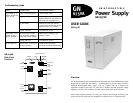
Back Panel
Functions
USER GUIDE
GN-675VA
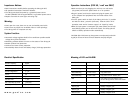
System
Power switch to “I”
Position & LED and
Alarm are OFF
Power switch to “I”
position & LED is
blinking YELLOW
Red LED Light on
Probable Cause
Power cord disconnected
City power failure
AC fuse blown
Control PCM error
GN-675VA input voltage
over HI transfer voltage or
under low transfer voltage
Control PCB error
Battery under or GN-675VA
as been shutdown
STATUS LINE MODEM
To Modem
From
Telephone
Line
Main
Switch
Outlet
Socket
Outlet
Socket
Outlet
Socket
AC Input
Socket
Fuse &
Spare
Fuse
Internet Protection
LAN
Interface
Troubleshooting Guide
Recommended Solution
Connect power cord
Turn the power switch to “O”
position. When the city power has
resumed, turn the power to “I.”
Remove the load from the GN-
675VA. Check the fuse near outlet,
replace the fuse if it is blown.
Call Dealer for Service
Make sure the voltage of city
power is correct.
Call Dealer for Service
Charge battery, shut down,
condition will release automatically.
Overview:
The GN-675VA protects your sensitive electronic equipment from power disturbances. A power
outage can occur when you least expect it – threatening the loss of critical data. The Genica
GN-675VA Uninterruptible Power Supply works as a battery back up to protect your
equipment and data in the event of a power loss. In addition, the ARV (automatic voltage
regulator) and built-in line conditioner provides stable voltage when power fluctuates.
Also includes modem protection! By routing your modem cable through the GN-675 your
modem will also be protected from damage by occurrences such as a lightning strike.