


15
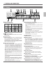
CCD
CCD
CCD
CCD
CCD
CCD
1 2 3 4 5 6
1 2 3 4 5 6
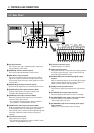
AC~IN
AC120V~50/60Hz
RS-232C
CAM SW
OUT
ALARM
IN
COM
COM
ALARM
REC OUT
ALARM
RESET
TAPE
END OUT
WARNING
OUT
CLOCK
RESET IN
SERIES
REC IN
SERIES
REC OUT
CLOCK
RESET OUT
REMOTE
MIC
IN
OUT
AUDIO
VIDEO
Y/C
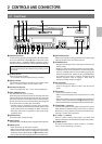
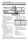
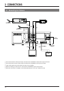
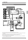
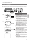
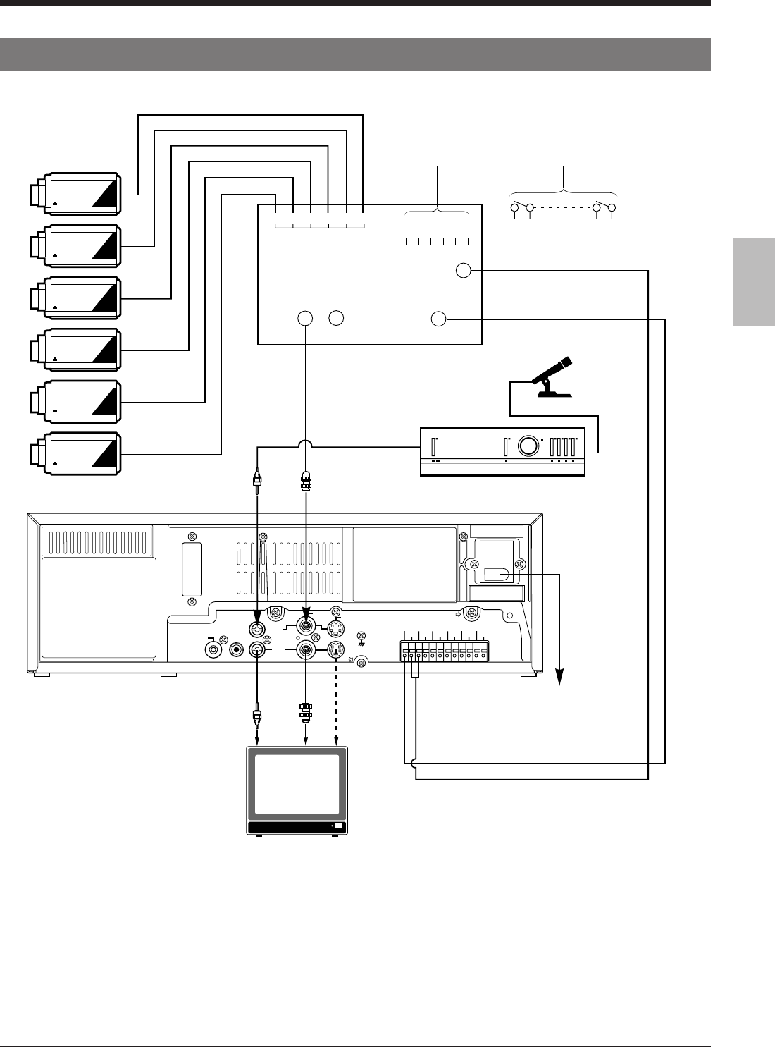
3-2 System Using Sequential Switcher
Video camera
Alarm sensor input
Alarm sensor
Microphone
Alarm signal output
Camera switching
signal input
Sequential switcher
Amplifier
AC 120 V
50/60 Hz
3 CONNECTIONS
Video output
Monitor TV
Provided
power cord
BNC
BNC
RCA
RCA
4pin
1 Connect video cameras and alarm sensor to a sequential switcher (frame switcher).
2 Connect the sequential switcher’s (frame switcher) alarm signal output, camera switching signal input and video output to
the SR-9090U.
3 Connect the monitor’s video/audio input connectors to the SR-9090U’s video/audio output connectors.
4 When the connection is complete, connect the power plug to an AC 120 V, 50/60 Hz outlet.
5 Synchro should be applied to all connected video cameras.
6 If you are connecting the camera switching signal input from a sequential switcher (frame switcher) to the SR-9090U, be
sure to set the <CAMERA SW> menu switch.
CAM SW
OUT
ALARM IN