


55
5.
SA-K97U
4.
3.
1.
2.
AC~IN
AC120V~50/60Hz
RS-232C
CAM SW
OUT
ALARM
IN
COM
COM
ALARM
REC OUT
ALARM
RESET
TAPE
END OUT
WARNING
OUT
CLOCK
RESET IN
SERIES
RESET IN
SERIES
RESET OUT
CLOCK
RESET OUT
REMOTE
MIC
IN
OUT
AUDIO
VIDEO
Y/C
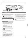
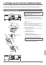
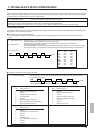
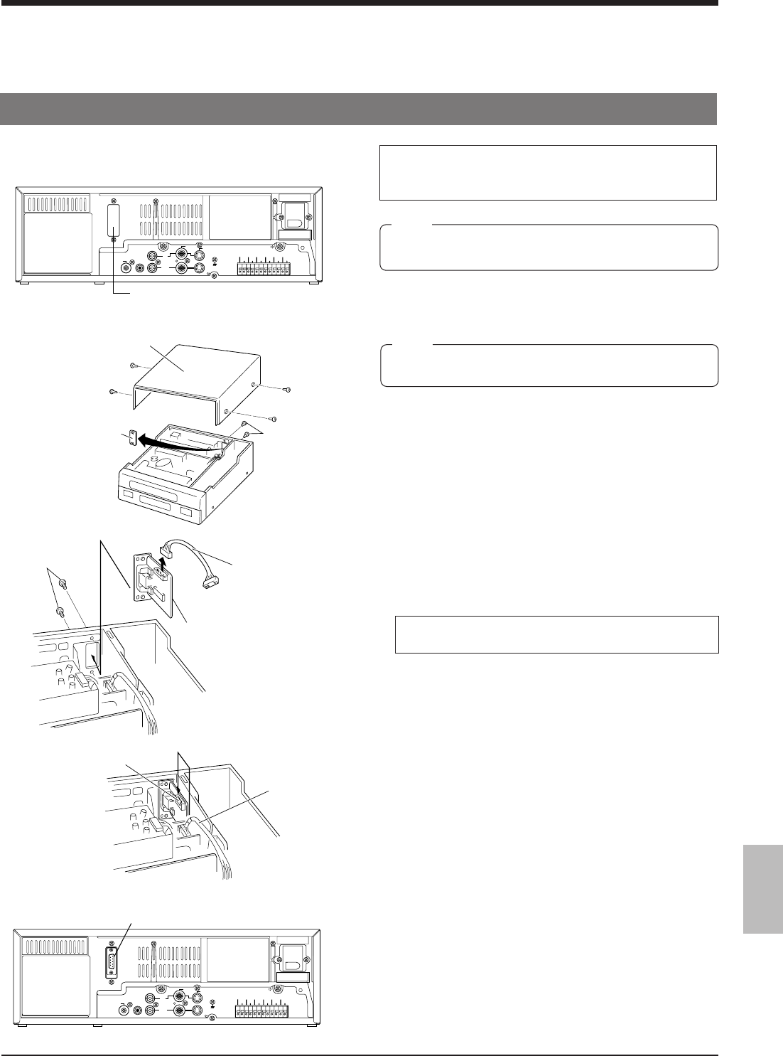
Functions that can be controlled with front panel buttons and switches can also be controlled from a personal computer when
the optional SA-K97U RS-232C interface board is installed. Operation status can also be monitored on the computer.
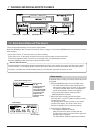
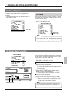
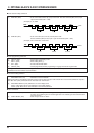
9-1 Installation of the SA-K97U
The procedure is shown below. However, to avoid
electric shock or injury, contact your local JVC
service center for details.
1. Detach the top cover.
Note:
Be careful when removing the top cover. The edges of
the cover could injure you if handled improperly.
Remove the 4 screws securing the top cover and lift it off.
2. Detach the plate in the VCR.
Remove the 2 screws on the rear panel. Detach the plate
from the inside of the VCR.
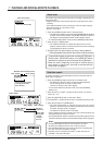
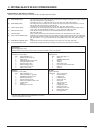
3. Detach the SA-K97U’s wire.
* The SA-K97U’s wire is not used.
4. Install the SA-K97U in the VCR.
Hold the board as shown in the illustration and secure it
using the screws removed previously in step 2.
5. Connect the VCR’s wire to the SA-K97U’s connector.
• Check the direction of the connector and connect it.
• Press both ends of the connector to firmly connect it.
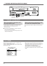
6. Replace the top cover on the VCR and secure it with the
four screws previously removed in step 1.
Note:
To avoid electric shock, be sure to unplug the power
cord from the AC outlet before installing the SA-K97U.
9 OPTIONAL SA-K97U RS-232C INTERFACE BOARD
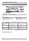
Rear panel
SA-K97U installation section
SA-K97U
AC~IN
AC120V~50/60Hz
RS-232C
CAM SW
OUT
ALARM
IN
COM
COM
ALARM
REC OUT
ALARM
RESET
TAPE
END OUT
WARNING
OUT
CLOCK
RESET IN
SERIES
RESET IN
SERIES
RESET OUT
CLOCK
RESET OUT
REMOTE
MIC
IN
OUT
AUDIO
VIDEO
Y/C
Top cover
Plate
Screws
Screws
Wire (not used)
Connector
Wire