


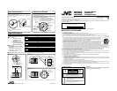

Precaution
ⅷThis equipment is intended for indoor use only. Do not use it
outdoors or at places that are exposed to rain or moisture.
ⅷDo not attach devices other than TK-C625U/E, TK-C655E, TK-
C676E, TK-C205(A)U/E, TK-C205VP(A)U/E, VN-C625U, VN-
C655U, TK-C210FWE, TK-C215V4U/E and TK-C215V12U/E to
this mount/bracket.
The suffix E of model No. specifies the exclusive variant for
European market.
ⅷInstall this mount/bracket horizontally. Do not tilt it during use.
ⅷDo not install or use the unit in the following places.
• In a place exposed to rain or moisture.
• In a temperature outsside the operating temperature range
(–10˚C to 50˚C (14˚F to 122˚F)).
• In a place where corrosive gasses are generated.
• In a place subject to vibration.
ⅷWhen attaching VN-C625U, VN-C655U to this mount/bracket,
please refer to the "INSTRUCTIONS" section of VN-C625U, VN-
C655U for procedures to install the converter unit.
ⅷPlease refer to the "INSTRUCTIONS" section of the camera in
use for procedures to attach the camera.
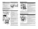
Installation Procedures
Camera
Mounting Plate
Ceiling Panel Assy
3.
1.
2.
5.
When a hole is not
made in the ceiling
4.Fall prevention
Reinforcement Angle
FRONT Mark
Protruding Part
Ceiling Panel
Assembly
Positioning
Hole
Front Mark
Top cover
Installing the Converter Unit
When using VN-C625U or VN-C655U, attach using the clamping bracket
inside the top cover of the converter unit (supplied with the camera).
Top cover
Converter Unit
Clamping Bracket
CAUTION
NOTE
Bolt (M4)
Safety cable Mount
Hole ( 4.5 mm)
CAUTION
Nut (M4)
Groove
Cable
Safety cable
Cables
Screws
(3 locations)
1.
Make a hole in the ceiling.
To route cables through the ceiling, make a hole of 30 mm ( 1 1/4)
in the ceiling.
2.
Route the safety cable and other cables
Route the safety cable and cables that is attached to the reinforce-
ment angle through the pendant mount.
When a hole is not made in the ceiling, route the cables through the
groove of the pendant Mount.
3.
Mount the Pendant Mount to the Ceiling.
Attach the pendant mount to the ceiling.
The camera may drop or images on the screen may appear shaky
if the ceiling material is not strong enough. In this case, reinforce
using a reinforcement materials.
4.
Connect the safety cable.
Upon removing the camera mounting plate, attach the safety cable
(not supplied) to the safety cable mount hole ( 4.5 mm ( 1/8")) at
the interior of the top cover using the M4 Bolt (not supplied) and M4
Nut (not supplied).
When attaching the camera mounting plate, ensure that the Front
mark on the camera mounting plate is facing a direction to the Front
mark on the top cover.
Pay particular caution to the length, strength, pull and material of
the safety cable in use to prevent the plate from falling.
5.
For attaching TK-C625U/E, VN-C625U, TK-C210FWE, TK-C215V4U/E and TK-C215V12U/E
Install the ceiling panel assembly
To install, align the protruding part of the ceiling panel assembly
with the ceiling panel assembly positioning hole near the Front mark
of the camera mounting plate. Ensure to tighten the screws (3
locations) assembled to the ceiling panel assembly.
The screws are assembled to the ceiling panel assembly in such
a way that they will not come off.
6.
Connect the Cables.
Connect cables to the camera.
For details, please refer to "INSTRUCTIONS" section of the camera
in use.
7.
Attach the camera's ceiling mount (outer case). (Not
applicable to TK-C205(A)U/E and TK-C205VP(A)U/E)
Attach the camera's ceiling mount (outer case) to the camera mount-
ing plate using the 4 screws (M4 x 10 mm) for TK-C210FWE, TK-
C215V4U/E and TK-C215V12U/E, and the other 4 screws (M4 x 20
mm) for the other cameras supplied with the pendant mount. Ensure
that the FRONT mark on the camera mounting plate aligns with the
Front mark on the ceiling mount.
It is not necessary to use the adapter ring supplied with TK-C215.
WB-S621U Pendant Mount
ⅷThese installation should be made by a qualified service person and should conform to all local codes.
ⅷThese installation should be in accordance with the National Electrical Code ANSI/NFPA 70.
ⅷUse the appropriate mounting hardware for the surface selected.
NOTE
WB-S622U Wall Mount
WB-S623U Ceiling Bracket
1.
Make a hole in the ceiling.
To route cables through the ceiling, make a hole of 30 mm ( 1 1/8") in the ceiling.
2.
Route the safety cable and other cables
Route the safety cable and other cables through the ceiling bracket. Please
refer to "About Fall Prevention" for procedures to install the safety cable.
When a hole is not made in the ceiling, route the cables through the hole at
one side of the Ceiling Bracket. Remove the cap covering the hole before
routing the cables through.
3.
Mount the ceiling bracket to the ceiling.
Mount the ceiling bracket to the ceiling.
4.
Connect the safety cable.
Upon removing the camera mounting plate, attach the safety cable (not supplied)
to the interior of the top cover using the M3 screw. (Refer to "About Fall Prevention".)
When attaching the camera mounting plate, ensure that the Front mark on the camera
mounting plate is facing a direction to the
Front
mark on the top cover.
5.
For attaching TK-C625U/E, VN-C625U, TK-C210FWE, TK-C215V4U/E
and
TK-C215V12U/E
Install the ceiling panel assembly
To install, align the protruding part of the ceiling panel assembly with the ceiling panel
assembly positioning hole near the Front mark of the camera mounting plate.
Ensure to tighten the screws (3 locations) assembled to the ceiling panel assembly.
The screws are assembled to the ceiling panel assembly in such a way that
they will not come off.
3.
1.
2.
3.
Cover Mounting
Screw
Cover
Camera Mounting
Plate
Ceiling Panel Assy
When a hole is not
made in the wall
Cap
Camera
Mounting
Plate
Ceiling Panel Assy
2.
5.
Reinforcement
Angle
5.
Ceiling Panel
Assembly
Positioning Hole
Front Mark
Protruding
Part
Front Mark
6.
Connect the cables.
Connect cables to the camera. For details, please refer to "INSTRUCTIONS" section of the camera in use.
7.
Attach the camera's ceiling mount (outer case). (Not applicable to TK-C205(A)U/E and TK-C205VP(A)U/E)
Attach the camera's ceiling mount (outer case) to the camera mounting plate using the 4 screws (M4 x 10 mm) for TK-C210FWE, TK-C215V4U/
E and TK-C215V12U/E, and the other 4 screws (M4 x 20 mm) for the other cameras supplied with the wall mount. Ensure that the Front mark
on the camera mounting plate aligns with the Front mark on the ceiling mount.
It is not necessary to use the adapter ring supplied with TK-C215.
1.
Front Mark
Front Mark
Protruding
Part
6.
Connect the cables.
Connect cables to the camera. For details, please refer to "INSTRUCTIONS" section of the camera in use.
7.
Attach the camera's ceiling mount (outer case). (Not applicable to TK-C205(A)U/E and TK-C205VP(A)U/E)
Attach the camera's ceiling mount (outer case) to the camera mounting plate using the 4 screws (M4 x 10 mm) for TK-C210FWE, TK-
C215V4U/E and TK-C215V12U/E, and the other 4 screws (M4 x 20 mm) for the other cameras supplied with the ceiling bracket. Ensure that
the Front mark on the camera mounting plate aligns with the Front mark on the ceiling mount.
It is not necessary to use the adapter ring supplied with TK-C215.
Top cover
Top cover
NOTE
NOTE
When a hole is not
made in the ceiling
Ceiling Panel
Assembly
Positioning Hole
Screws
(3 locations)
The camera may drop or images on the screen may appear shaky if the ceiling
material is not strong enough. In this case, reinforce using a reinforcement materials.
CAUTION
Screws
(3 locations)
Safety cable
Cables
The camera may drop or images on the screen may appear shaky if the ceiling
material is not strong enough. In this case, reinforce using a reinforcement materials.
CAUTION
Groove
Safety
cable
Cables
1.
Make a hole
To route cables through the wall, make a hole of 30 mm ( 1 1/8") in the wall.
2.
Route the safety cable and other cables
Open the cover and route the safety cable and other cables through this wall mount.
Please refer to "About Fall Prevention" for procedures to install the safety cable.
When a hole is not made in the wall, route the cables pulled to the wall stand
through the groove of the Wall Mount.
3.
Attach the wall mount to the wall
Attach the wall mount to the wall.
4.
Connect the safety cable.
Upon removing the camera mounting plate, attach the safety cable (not
supplied) to the interior of the top cover using the M3 screw. (Refer to "About
Fall Prevention".)
When attaching the camera mounting plate, ensure that the Front mark on the camera
mounting plate is facing a direction to the
Front
mark on the top cover.
5.
For attaching TK-C625U/E, VN-C625U, TK-C210FWE, TK-C215V4U/E and TK-C215V12U/E
Install the ceiling panel assembly
To install, align the protruding part of the ceiling panel assembly with the ceiling panel
assembly positioning hole near the Front mark of the camera mounting plate.
Ensure to tighten the screws (3 locations) assembled to the ceiling panel assembly.
The screws are assembled to the ceiling panel assembly in such a way that
they will not come off.
NOTE
NOTE