12
4 GETTING ACQUAINTED
PF
F LOCK
A
1
C
H
1/R
E
C
2
C
H
2/R
EC
3
C
H
3
/R
E
C
4
TO
N
E
/S
E
L
5
M
ET
E
R
6
C
T
C
S
S/S
EL
7
N
B
/LE
V
EL
8
AG
C
/O
FF
9
F
IN
E/S
TE
P
.
D
C
S
/S
E
L
0
S
H
IF
T
/O
F
F
S
E
T
EN
T
SEND
PHONES
MIC
AT
ANT1/2
PROC
LEVEL
VOX
ATT
PRE
LEVEL
LEVEL
LEVEL
MANUAL
LO/
WIDTH
HI/
SHIFT
N.R.
A.N.
B.C
.
F
U
N
C
CALL
C.IN
CLR
MAIN
AUTO
CAR
TX MONI
DELAY
NAR
REV
MIC
PWR
KEY
LSB
USB
CW
FSK
FM
AM
SUB
DISP
SEL
1MHz
CTRL
MR
MG.SEL
M.IN
QUICK MEMO
M
/S
R
EV
TRACE
M
AIN
M
AN
UA
L
R
F
A
F
SQ
L
SU
B
C
H
MULTI
BC
M
AIN
G
AIN
VFO/CH
MENU
TF-
SET
MAIN SUB
SG.SEL
SCAN
M VFO
M.IN
RIT
CW TUNE
9.6k STA
RIT/SUB
CON
XIT
ALT
SET
CLEAR
P. C . T
_
+
HF/VHF/UHF ALL MODE MULTI BANDER TS-2000
S
A
T
L
A
/B
VFO/M
SPLIT
A=B
474654 55 4445
5352 51504948
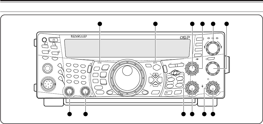
$4 RIT/SUB control
After switching the RIT or XIT function ON, turn this
control to select the desired frequency offset
{pages 38, 40}.
Turn to adjust the sub-receiver frequency when the
RIT and XIT functions are switched OFF and the sub-
receiver is switched ON {page 45}.
$5 MANUAL BC control
Turn to adjust the audio notch frequency while the
DSP beat cancel function is set to the manual
frequency adjustment mode {page 56}.
$6 MAIN RF GAIN control
Turn to adjust the radio frequency gain for the main
transceiver {page 18}.
$7 MULTI/ CH control
In VFO mode, rotate to step the operating frequency
up or down {page 37}. In memory channel mode,
rotate to select a memory channel {page 58}. Also
used for selecting Menu numbers when accessing the
Menu mode {page 21} and as a selector to choose
settings for various functions activated by front panel
buttons. The MULTI/ CH LED lights when the
setting(s) can be changed using the MULTI/ CH
control.
$8 MAIN SQL control
Used for muting (“squelching”) the speaker, the head
phones and AF output on ACC2 (13-pin DIN
connector) when no receive signal is present on the
main transceiver {page 19}.
$9 MAIN AF control
Turn to adjust the volume on the main transceiver
{page 19}.
%0 SUB SQL control
Used for muting (“squelching”) the speaker, head
phone and AF output on ACC2 (13-pin DIN
connector) when no receive signal is present on the
sub-receiver {page 46}.
%1 SUB AF control
Press to switch the sub-receiver ON or OFF. When it
is ON, the SUB-receiver LED lights orange.
Turn to adjust the volume for the sub-receiver.
%2 LO/ WIDTH control
Turn clockwise/ counterclockwise to increase/
decrease the value for the low cut-off DSP filter
frequency or the filter bandwidth (CW/ FSK). The
selected value appears on the main dot-matrix
display {page 55}.
%3 HI/ SHIFT control
Turn clockwise/ counterclockwise to increase/
decrease the value for the high cut-off DSP filter
frequency or the Shift frequency. The selected value
appears on the sub dot-matrix display {page 55}.
%4 MAIN band LED
Lights green while the main transceiver’s squelch is
open. Lights red while transmitting on the main
transceiver’s VFO band.
%5 SUB band LED
Lights green while the sub-receiver’s squelch is open.
Lights red while transmitting on the sub-receiver’s
VFO band.


