


21
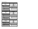
CABLE INFORMATION
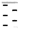
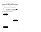
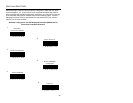
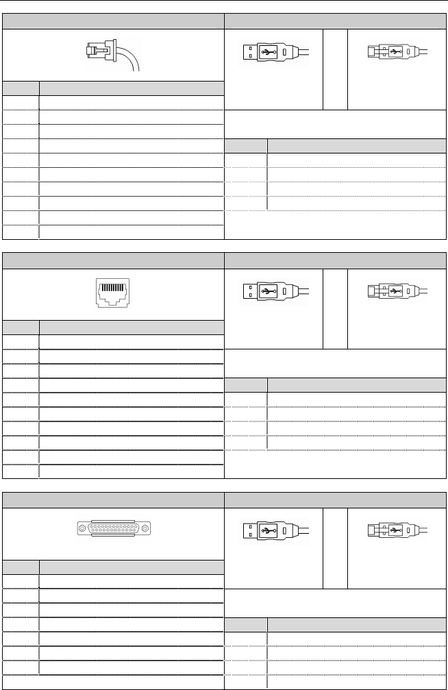
Scanner Connector End USB Connector End
10-Pin RJ45 Male
Type A
Locking Type A
Pin Function
MX009-2MA7x
and MX009-2MB7x and
1 Ground
MX009-2MA8x
or
MX009-2MB8x
2 TXD
3 RXD
x = C (coiled) or S (Straight) cable
4 RTS Pin Function
5 CTS 1 Vbus
6 DTR/LP 2 D-
7 Reserved 3 D+
8 LP Data 4 Ground
9 +5 VDC From Transformer
10 SHD/GND
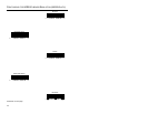
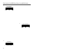
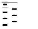
Scanner Connector End USB Connector End
10-Pin RJ45 Female
Type A
Locking Type A
Pin Function
MX009-2FA7x
and MX009-2FB7x and
1 Ground
MX009-2FA8x
or
MX009-2FB8x
2 TXD
3 RXD
x = C (coiled) or S (Straight) cable
4 RTS Pin Function
5 CTS 1 Vbus
6 DTR/LP SRC 2 D-
7 Reserved 3 D+
8 LP Data 4 Ground
9 +5 VDC From Transformer
10 SHD/GND
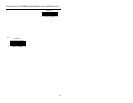
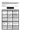
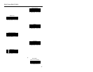
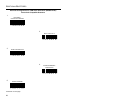
Scanner Connector End USB Connector End
25 Pin Female D-Sub
Type A
Locking Type A
Pin** Function
MX009-2WA7x
and MX009-2WB7x and
2 RS232 Receive
MX009-2WA8x
or
MX009-2WB8x
3 RS232 Transmit
7 Signal Ground
x = C (coiled) or S (Straight) cable
13 Earth Ground Pin Function
14 Power GND #1 1 Vbus
19 Power In 2 D-
25 Power GND #2 3 D+
** Pins not shown are “No Connect”. 4 Ground
1
10
4
1
4
1
1 10
4
1
4
1
4
1
4
1
1 13
14 25