


16
16
Additional connection cables are not
provided with the TV. They should be
available at most electronic stores.
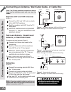
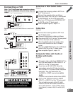
Connecting an Antenna, Wall Outlet Cable, or Cable Box
Connecting an Antenna, Wall Outlet Cable, or Cable Box
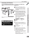
Separate UHF and VHF Antennas
(Figure 1)
1
Connect the UHF and VHF antenna leads
to the UHF/VHF combiner.
2
Push the combiner onto ANT-A on the TV
back panel.
UHF/VHF combiners are not provided
with the TV. They are available at most
electronic stores.
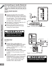
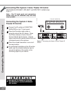
Twin Lead Antenna, Coaxial Lead
Antenna, or Wall Outlet Cable
For antenna with twin at leads (Figure 2)
1
Connect the 300ohm twin leads to the
transformer.
2
Push the 75ohm side of the transformer
onto ANT-A on the TV back panel.
300ohm to 75ohm matching transformers
are not provided with the TV. They are
available at most electronic stores.
For cable or antenna with coaxial lead (Figure 2)
3
Connect the incoming cable to ANT-A on
the TV back panel.
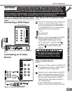
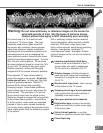
Cable Box
(Figure 3)
1
Connect the incoming cable to ANT-A on
the TV back panel.
Connect two coaxial cables as follows:
2
One from LOOP-OUT on the TV back panel
to IN on the cable box back panel.
3
One from OUT on the cable box back panel
to ANT-B on the TV back panel.
CO MPONE NT
480i / 480P/ 1080i
AU DIO -
RI GHT
L EFT /
( MONO)
AU DIO -
DT V
(Y PbPr/ GBRHV )
MONITOR
I NP UT
OUT
2
1
ANT-A
ANT-B
LOOP
OUT
480i / 480 P /1080 i
AUDI O-
RIG HT
AUDIO-
LEF T/
(MONO)
VI DE O
S-VIDEO
2
IR EMITTER REPEATER
Y
P r
Pb
V
H
Y
G
Pb
B
P r
R
External
Antenna
or Cable
Back
Side
Flat Twin Lead
UHF Antenna
(Channels 14-69)
VHF Antenna
(Channels 2-13)
300 Ohm to
75 Ohm
Combiner
Flat Twin Lead
TV back panel
UHF
VHF
AN T - A
TV back panel (Detailed View)
2
1
Figure 1. Connecting separate UHF and VHF antennas.
Note: See page 5 for Outdoor Antenna Grounding
COMP ONE NT
480i / 480P/ 1080i
AUDI O-
RI GHT
LE FT /
(MONO)
AUDI O-
DT V
(Y PbPr/ GBRHV)
MONITOR
I NP UT
OUT
2
1
ANT-A
ANT-B
LOOP
OUT
480i / 480P /1080i
AUDI O-
RIG HT
AUDIO-
LEF T/
(MONO)
VI DE O
S-VIDEO
2
IR EMITTER REPEATER
Y
P r
Pb
V
H
Y
G
Pb
B
P r
R
300 Ohm Flat
Twin Lead
Optional 300 Ohm to 75 Ohm
Matchin
g
Transformer
75 Ohm
Coaxial Cable
1
2
3
TV back panel (Detailed View)
AN T - A
Figure 2. Connecting twin lead antenna, coaxial lead
antenna, or wall outlet cable.
Note: See page 5 for Outdoor Antenna Grounding
Figure 3. Connecting the cable box.
Note: See page 5 for Outdoor Antenna Grounding
COMP ONE NT
480i / 480P/ 1080i
AUDI O-
RI GHT
LE FT /
(MONO)
AUDI O-
DT V
(Y PbPr/ GBRHV )
MONITOR
I NP UT
OUT
2
1
ANT-A
ANT-B
LOOP
OUT
480i / 480P /1080i
AUDI O-
RIG HT
AUDIO-
LEF T/
(MONO)
VI DE O
S-VIDEO
2
IR EMITTER REPEATER
Y
P r
Pb
V
H
Y
G
Pb
B
P r
R
OUT
Cable Box
back panel section
IN
Incoming
Cable
1
2
3
ANT- A
ANT-B
LOOP
OUT
TV back panel (Detailed View)
Note: The TV back panel and connections shown
here are for reference only and may vary by
model.
Note: If you have a digital cable box, refer to your
Digital Cable Box owner’s guide for instructions on
optimal connections to this TV.