


20
20
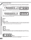
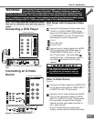
Connecting a DTV Receiver
Connecting a DTV Receiver
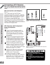
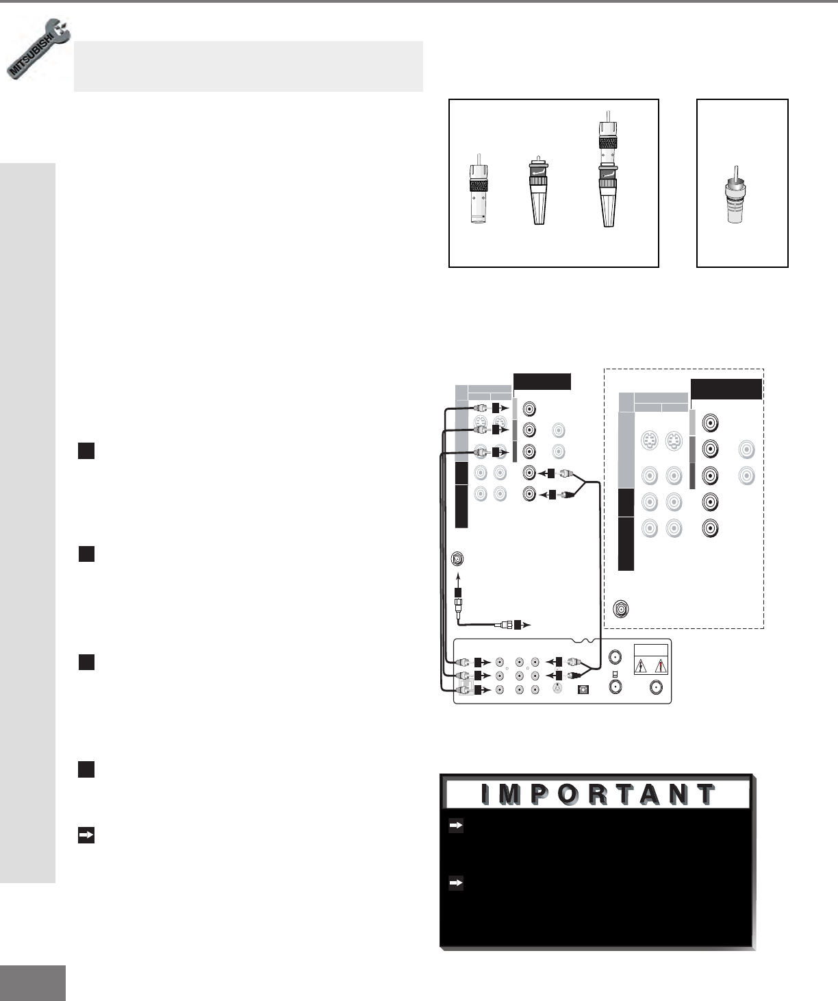
DTV Connectors and Adaptors
(Figure 1)
The TV back panel has ve RCA-type
connectors for the DTV connection. The back
panel of your DTV receiver may use RCA-type
connectors or BNC-type connectors. If your
DTV receiver comes with BNC type
connections, you will need to purchase BNC to
RCA adaptors to connect the TV to the DTV
receiver. These adaptors should be available at
most electronic supply stores.
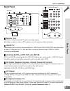
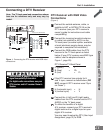
DTV Receiver with Component
Video Connections
(Figure 2)
1
Connect the outside antenna cable, or
satellite to ANT or SATELLITE IN on the
DTV receiver (see your DTV receiver
owner’s guide for instructions and cable
compatibility).
2
Connect the incoming terrestrial antenna
or cable (not satellite) to ANT-A on the
TV back panel (a coaxial splitter, available
at most electronic supply stores, may be
required to complete this installation).
3
Connect the RCA-type cables from the
outputs on the DTV receiver to DTV INPUT
Y/Pb/Pr or Satellite/ Box on the TV back
panel. You may need to set the DTV Input
Assignment, page 31, to Y/Pb/Pr.
4
Connect the L (left) and R (right) audio
cables from the DTV receiver to DTV
AUDIO on the TV back panel.
To utilize the benets of a digital
A/V receiver, connect your DTV receiver’s
digital audio out to a digital input on your
digital A/V receiver. Component 1 and 2
may also be used for 1080i component.
See Appendix B, page 67, for
component video signal compatibility
information.
For digital audio connections, see your
DTV receiver and A/V receiver Owner’s
Guides.
BNC to
RCA BNC
Adaptor Connector
Adaptor
Fitted to
Connection
RCA
Connector
or
Figure 1. DTV connectors and adaptors.
Figure 2. Connecting the DTV receiver with component
Video Connections.
AUDIO AUDIO
VIDEO VIDEO
L
R
L
R
Y
Pr
Pb
S-VIDEO
VCR
CONTROL
DIGITAL
AUDIO OUT
PHONE JACK
RF
REMOTE
SATELLITE IN
IN FROM ANT
OUT TO TV
CH 3
CH 4
CAUTION
RISK OF ELECTRICAL SHOCK
DO NOT OPEN
DT V
(YPbPr/ GBRHV)
IN PU T
2
1
ANT- A
480i / 480P /1080i
AUDIO-
RI GHT
AUD IO-
LE FT /
(MONO)
Y
G
Pb
B
P r
R
VIDEO
S-VIDEO
White
Red
3
3
3
4
4
4
4
3
3
3
Incoming Antenna,
or Cable.
White
Red
2
2
DT V
(YPbPr/ GBRHV)
IN PUT
2
1
ANT-A
480i / 480P /1080i
AUDIO-
RIG HT
AUDIO-
LE FT /
(MONO)
Y
G
Pb
B
P r
R
VIDEO
S-VIDEO
TV back panel (Detailed View)
Note: The TV back panel and connections shown
here are for reference only and may vary by
model.