


22
22
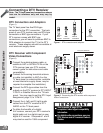
COMPONENT
480i/ 480P/ 1080i
AUDIO-
RIGHT
LEFT /
(MONO)
AUDIO-
DT V
(YPbPr/ GBRHV)
MONITOR
IN PU T
OUT
2
1
ANT-A
ANT-B
LOOP
OUT
480i / 480P /1080i
AUD IO-
RI GHT
AUD IO-
LE FT /
(MONO)
V ID EO
S-VIDEO
2
IR EMITTER REPEATER
Y
P r
P b
V
H
Y
G
Pb
B
P r
R
Other A/V Device
1
Ferrite
Core
A/V Receiver
IR EMITTER REPEATER
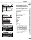
TV back panel (Detailed View)
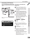
D IG ITA L
SURROU ND
S
CH
D IG ITA L
SURROU ND
S
AH
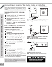
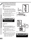
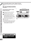
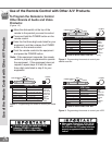
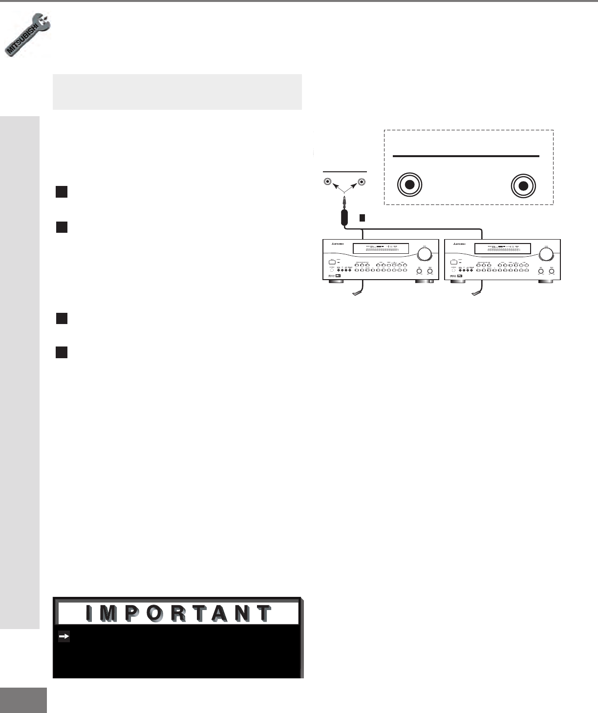
Figure 1. Connecting the System 4 Home Theater IR
Control.
See page 57 for details on using the
TV’s IR emitter to control a Mitsubishi
A/V receiver.
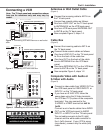
1
Connect the IR emitter to IR EMITTER
REPEATER on the TV back panel.
2
Place the IR emitter cable under or
along the side of the A/V device. Place
the IR lens directly in front of the A/V
device infrared signal receiver. Infrared
signal receivers are usually behind the front
translucent panel of the receiver.
3
Place the unused transmitter in an out-of-
the-way location.
4
For permanent installation of the IR emitter
cable, use the included adhesive tape to
secure the bottom of the emitter to the
anchoring object of your choice.
Connecting the System 4 Home Theater IR Control
(Applicable for WS-55411, WS-65411 and WS-73411 models only)
(Figure 1)
Connecting the System 4 Home Theater IR Control
Connecting the System 4 Home
Theater IR Control.
Note: The TV back panel and connections
shown here are for reference only and may
vary by model.