


— 1 — — 2 — — 3 —
TCF-142-M(-T), TCF-142-S(-T)
RS-232/422/485 to Fiber Converter
Quick Installation Guide
Eighth Edition, July 2006
1. Overview
Introduction
The TCF-142 series (Ver. 3.1 or later) converters are equipped with a
multiple interface circuit that can handle RS-232, or RS-422/485 serial
interfaces, and multi-mode or single-mode fiber. The TCF-142 converters
extend serial transmission distance up to 5 km (TCF-142-M, with
multi-mode fiber) or up to 40 km (TCF-142-S, with single-mode fiber).
The TCF-142 must be configured to transmit a particular serial interface
(e.g., RS-232 and RS-485 signals cannot be transmitted at the same time).
Why convert serial to Fiber?
Fiber communication not only extends the communication distance, but
also provides many advantageous features.
IMMUNITY FROM ELECTRICAL INTERFERENCE: Fiber is not
affected by electromagnetic interference or radio frequency interference.
It provides a clean communication path and is immune to cross-talk.
INSULATION: Optical fiber is an insulator; the glass fiber eliminates the
need for using electric currents as the communication medium.
SECURITY: Fiber cannot be tapped by conventional electric means and
is very difficult to tap into optically. Furthermore, radio and satellite
communication signals can be captured easily for decoding.
RELIABILITY & MAINTENANCE: Fiber is immune to adverse
temperature and moisture conditions, does not corrode or lose its signal,
and is not affected by short circuits, power surges, or static electricity.
Reverse Power Protection
The Reverse Power Protection feature provides extra protection against
accidentally connecting the power cables to the wrong terminal. The
converter is designed to detect automatically which power wire is positive
and which is negative, and then adjust the power supply accordingly.
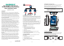
Ring Mode
To allow one half-duplex serial device to communicate with multiple
half-duplex devices connected to a fiber ring, you should configure the
TCF-142 for “ring mode” by setting DIP switch “SW4” to the “On”
position. The Tx port of a particular TCF-142 unit connects to the
neighboring converter’s Rx port to form the ring. Note that when one
node transmits a signal, the signal travels around the ring until it returns
back to the transmitting unit, which then blocks the signal. Users should
ensure that the total fiber ring length is less than 100 km when using
TCF-142 series converters.
RS-232
RS-232RS-422 RS-485
TCF-142
TCF-142TCF-142
Tx
TxTx Tx
Rx
Rx RxRx
TCF-142
5210
TCF-142-S
sw
Rx Tx
PWR
FiberTx
Fiber Rx
Serial to Fiber Converter
RS-232/422/485
T+
T-
R+/D+
R-/D-
Tx
Rx
GND
RS-422/485RS-232
12-48V
V+
V-
5210
TCF-142-S
sw
Rx Tx
PWR
FiberTx
Fiber Rx
Serial to Fiber Converter
RS-232/422/485
T+
T-
R+/D+
R-/D-
Tx
Rx
GND
RS-422/485RS-232
12-48V
V+
V-
5210
TCF-142-S
sw
Rx Tx
PWR
FiberTx
Fiber Rx
Serial to Fiber Converter
RS-232/422/485
T+
T-
R+/D+
R-/D-
Tx
Rx
GND
RS-422/485RS-232
12-48V
V+
V-
5210
TCF-142-S
sw
Rx Tx
PWR
FiberTx
Fiber Rx
Serial to Fiber Converter
RS-232/422/485
T+
T-
R+/D+
R-/D-
Tx
Rx
GND
RS-422/485RS-232
12-48V
V+
V-
DIP Switch Selectable Terminator
The termination resistor for many products of this type is set by a jumper
located inside the product’s casing. To disable or change the resistor’s
strength, the user must open the casing to reset the jumper. MOXA offers
a better solution, since TCF-142’s termination resistor is set with a DIP
Switch located on the outside of the converter’s casing.
No Configuration Required for Baudrate Settings
The TCF-142 works under any baudrate from 300 bps to 921.6 Kbps. The
TCF-142 simply converts the signal back and forth between serial
(RS-232, RS-422, or RS-485) and fiber, and since the TCF-142 does not
need to interpret the signal, it does not need to know the baudrate of the
transmitting device. For this reason, TCF-142 does not have any DIP
switches or jumpers for setting the baudrate.
2. Features
y “Ring” or “Point to Point” transmission
y Extend RS-232/422/485 transmission distance:
> up to 40 km with single-mode—TCF-142-S
> up to 5 km with multi-mode—TCF-142-M
y Compact size
y Decrease signal interference
y Protect against electronic degradation and chemical corrosion
y Supports a baudrate up to 921.6 Kbps
y Extended operating temperature from -40 to 75°C (for -T models)
3. Package Checklist
Before installing the TCF-142, verify that the package contains the
following items:
y TCF-142-S or TCF-142-M Fiber Converter
y Quick Installation Guide
y 7-contact terminal block connector
y 3-contact terminal block connector
Notify your sales representative if any of the above items is missing or
damaged.
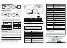
4. Dimensions and Appearance
TCF-142 fiber converters are easy to set up and use. The serial terminal
block of one of the converters connects to your computer, the serial
terminal block of the other converter connects to your serial device, and
the two converters are connected by fiber cable(s).
NOTE
Electrostatic Discharge Warning!
To protect the product from damage due to electrostatic
discharge, we recommend wearing a grounding device when
maintaining TCF-142.
100.4 mm (3.95 in)
22.0 mm
(0.87 in)
21.3 mm
(0.8 in)
42.3 mm
(1.67 in)
67 mm (2.64 in)
78 mm (3.07 in)
12.5 mm
(0.49 in)
25 mm (0.98 in)
O 6 mm
(0.24 in)
O 4 mm
(0.16 in)
O 7 mm
(0.28 in)
90.2 mm (3.55 in)
67 mm (2.64 in)
22.0 mm
(0.87 in)
ON
123
4
5. Wiring Examples
Connecting the Power Supply
Before using the TCF-142, you must first connect the DC power supply
to the power supply terminal block located on the bottom side of the
TCF-142. The TCF-142 uses a DC power supply.
Connecting RS-422 or 4-wire RS-485 Serial Devices
RS-422/485
Rx
Tx Rx
Tx
RS-422/485
Tx-
Tx+
Rx-
Rx+
GND
R-
R+
T-
T+
GND
TCF-142
TCF-142
Serial
Device
Serial
Device
T-
R+
R-
GND
T+
Rx-
Tx+
Tx-
GND
Rx+
Copper CopperFiber
P/N: 1802001420600