


1
42G1215A-XT-1-2 and
42G1215A-XT-1-3
OM-20000154 Rev 1 December 2013
ANTENNA GUIDE
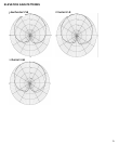
The 42G1215A-XT-1-3 and 42G1215A-XT-1-2 are active antennas designed to operate at the GPS L1 and
L2 frequencies, 1575.42 and 1227.60 MHz and across the L-Band from 1525 to 1560 MHz. The antennas
are aircraft certified for navigation. This guide provides the information needed to install and use the
antenna.
ADDITIONAL EQUIPMENT REQUIRED
• A device with an antenna input port that both receives the RF signal and provides 2.5 to 24.0 VDC to the
antenna is required to set up the 42G1215A-XT-1-3 and 42G1215A-XT-1-2. (NovAtel GPS receivers
provide the necessary power through their antenna RF connectors.)
• Coaxial cable with a male TNC connector
INSTALLING THE ANTENNA
Both the input DC power and the output RF signal flow over a single coaxial cable connected to the unit's
TNC female connector.
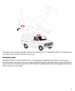
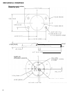
The antenna is attached to a surface by means of an ARINC-743 Bolt Pattern.
Four screws pass through the housing of the antenna.
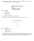
Install the antenna as follows:
1. Place the o-ring into the groove on the antenna base (o-ring supplied).
2. Pre-drill the mounting holes and the connector hole on the surface. Refer to the Mechanical Drawings
section of this guide for details on the ARINC-743 mounting pattern.
User-supplied o-ring grease can be used to hold the o-ring in the groove
during installation.