


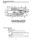
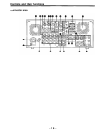

<Front Panel Center Section>
REC INHIBIT lamp
This lights when the REC INHIBIT switch in the front panel bottom section is at ON or
when the accidental erasure prevention mode has been set for the cassette.
In this state, neither recording nor editing is possible.
STAND BY button
When this is pressed, the same tension as in the regular stop mode is applied to the tape,
and while the head drum continues to rotate, the button’s lamp lights to indicate that the
standby ON mode is established.
In the standby OFF mode, the half-loading mode is established.
When this button is pressed in the stop mode, the standby OFF mode is established, the
half-loading mode is established. The lamp in the button now goes off. When the unit
remains in the stop mode for longer than a predetermined period, the standby OFF mode
is automatically established in order to protect the tape.
When this button or the STOP button is pressed in the standby OFF mode, the standby
ON mode is established.
When a button other than the STOP button is pressed, the mode corresponding to the
button pressed is established.
On-screen settings are available for the transfer time to the standby OFF mode.
PLAYER/RECORDER buttons
These buttons are operated when editing operations are conducted using the unit as the
recorder and a VTR equipped with an RS-422A serial interface remote control connector
(9 pins). Neither button functions when the unit is used on its own.
PLAYER button:
When this button is pressed, its lamp lights, and the player connected
to the unit can be operated by remote control. The unit’s editing and
tape transport buttons now control the player’s functions.
RECORDER button:
When this button is pressed, its lamp lights, and the editing and tape
transport buttons control the recorder’s (= the unit’s) functions.
Both lamps light, and the recorder functions as the master unit for Parallel Run operations
if the PLAYER or RECORDER button is pressed while “ENA” has been selected for setup
menu No. 200 (PARA RUN). [However, external control can no longer be exercised from
the REMOTE connector (9-pin) when this setting has been made.]
TC/CTL switch
By pressing this switch, what appears on the counter display is changed between TC and
CTL.
When TC is selected, either the TC or UB value is displayed depending on the position
selected by the TC/UB switch.
TC/UB switch
This selector switch determines whether the value of TC or UB appears on the counter
display when the TC/CTL switch has been set to TC.
INT/EXT switch
INT:
For using the built-in time code generator.
EXT:
For using the time external code which is input from the time code input connector or
the video signal VITC. The selection is set at the setup menu No. 505 (EXT TC SEL).
TAPE/EE switch
<In the stop mode>
TAPE:
For outputting the signals played back from the tape.
EE:
For outputting the input signals selected by the INPUT SELECT switch.
<ln the editing*/recording mode>
TAPE:
For outputting the simultaneous playback signals.
EE:
For outputting the input signals selected by the INPUT SELECT switch.
* The SETUP menu No. 310 (CONFI EDIT) setting is required.
-9-