


– 15 –
Controls and their functions
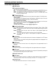
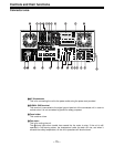
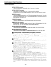
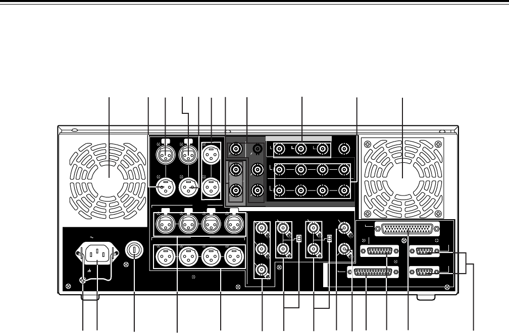
Connector area
SIGN
AC IN
FUSE
TC
IN IN L
OUT
CH 1
AUDIO IN
CH 2 CH 3 CH 4
VIDEO OUT
(WFM)
ON
OFF
75≠
ON
OFF
75≠
(SUPER)
1
2
3
SD REF IN
CH1·2
AUDIO
OUT
CH3·4 CH5·6 CH7·8
HD REF IN HD REF OUT
SD
REF OUT
RS-232C
ENCODER
REMOTE
REMOTE
IN/OUT
REMOTE
OUT
PARALLEL
CH 1 CH 2 CH 3 CH 4
OUT R
CUE MON
PUSH
PUSH PUSH PUSH
125V 5A
L
GD
CH1·2
AUDIO
IN
CH3·4 CH5·6 CH7·8
OUT 1
OUT 1
(SUPER)
(SUPER)
IN
OUT 2 OUT 3
SD SDI
ANALOG
DIGITAL AUDIO
SD SDI
OPTION
(OPTION)
HD SDI
HD SDTI
R
E
M
O
T
E
IN
OUT
OUT 2
OUT 3
AUDIO OUT
PUSH PUSHPUSH
PUSH
4
1
2
3
5
6
7
8
9
=
<
>
:
;
A
?@ B
C
D
E
F
G
H
4
1 AC IN connector
This is for connecting the unit to the power outlet using the power cord provided.
2 SIGNAL GND terminal
This terminal is connected to the signal ground terminal of the connected unit in order to
reduce noise. It is not connected to ground for safety purposes.
3 Fuse holder
This contains a fuse.
4 Fan motor
This is for cooling the unit.
The W lamp lights when trouble has caused the fan motor to stop. If the unit is still
operated in the warning status, the temperature inside the deck will rise, and when it
exceeds the safety temperature, all the unit’s operations will be shut down.