


10
Front panel
>
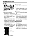
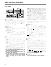
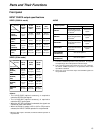
Time code display
The data, VTR status information, tape format
information or warning information which
corresponds to the direct menu buttons
@
appear
on this display. (See page 16 for details of the
displays.)
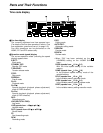
?
UNITY lamps
VIDEO UNITY lamp
This lights if the UNITY level applies for all the HD
or SD output levels.
AUDIO UNITY lamp
This lights if the UNITY level applies for the PCM
or CUE AUDIO input or output level. (The lighting
of the lamp complies with the setting selected for
setup menu item No.142 (AUDIO UNITY).)
@
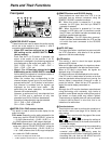
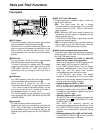
Direct menu buttons
These buttons are used to switch directly to the
function menus on the time code display.
HOME: The most basic settings of recording,
playback and time code operations are selected
on this menu.
VIDEO: The basic input and output settings for the
video signals are selected on this menu. The
level of the HD output signals can also be
adjusted on this screen.
AUDIO: The basic input and output settings for the
audio signals are selected on this menu.
PF1: This enables user-defined menu items to be
registered in the function keys.
PF2: This enables user-defined menu items to be
registered in the function keys.
TC: The settings related to the time code are
selected on this menu. Superimposing the time
code on the display can also be set on this
screen.
Parts and Their Functions
POWER
OFF
ON
HEADPHONES
PUSH
LOCK
FULL
CH CONDITION
MONITOR
FULL/FINE
REMOTE
LR
9P 50P
RS-232C
CH12345678
CUE
XL/L/M
-
cassette
Do not insert S-cassette
without adapter
EJECT
AUDIO CH SELECT
SHIFT
ABC DEF GHI
JKL MNO PQRS
PREVIEW/
REVIEW
PRE-
ROLL
A IN A OUT
HOME RF1 ASSEM
ADJUST
SHTL
REV FWD
VARJOG
STAND BY
RECORDER INPUT CHECK
PLAYER
SERVO
EDIT PLAY REC
REW STOP FF
REC INHIBIT
PUSH-INTER
INSERT
RF2
VIDEO
UNITY TC CUE
AUDIO
UNITY DIAG MENU
TRIM
SET
IN
OUT
AUTO
EDIT
789
456BS
TUV WXYZ
123
ENT
0CTF
F1 F2 F3 F4 F5 F6
CH
1
CH
5
CH
2
CH
6
CH
3
CH
7
CH
4
CH
8
FULL
REC P8 REC P8 REC P8 REC P8
> A C
? B
@
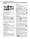
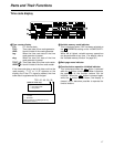
CUE: This enables up to 60 cue points to be set. In
the PAGE mode, 10 pages with 6 cue points on
each page are provided so that the cue points can
be managed on a page-by-page basis.
DIAG: This enables the warnings and hour meter
displays to be checked. On the SHIFT screen, the
error log files can be checked and deleted.
MENU: On this menu, it is possible to transfer
operation to the screen on which operations
(adjustments and saving data in or loading it from
the internal memory and IC card) relating to the
SYSTEM and SETUP menus are to be performed.
See page 38 and following for further details on
each of the function menus.
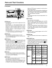
A
ASSEM button
This button is used to perform assemble editing.
When it is pressed, the <ASSEMBLE> menu
appears on the time code display. Setting ASSEM
to ON using enables assemble editing, and the
lamp of the ASSEM button lights.
Even after operation is transferred by another direct
menu, the assemble mode will remain established
while the ASSEM button lamp is lighted.
To release the assemble mode, select OFF as the
ASSEM setting on the <ASSEMBLE> menu.
The ASSEM button lamp now goes off and the
assemble mode is released.
B
INSERT button
This button is used to perform insert editing.
When it is pressed, the <INSERT> menu appears
on the time code display, and the function menu for
selecting the signals to be edited is displayed.
To select the signals to be edited, press the
function key, and highlight the display. The
highlighted display indicates that those signals are
selected.
To release the selection, press the same function
key again.
Use to to select the V, A1, A2, A3, A4 and
CUE signals; use + to to select the
A5, A6, A7, A8 and TC signals.
C
ADJUST dial
This is used for the menu and other operations.
F6F2SHIFT
F6F1
F1
F1