


122
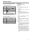
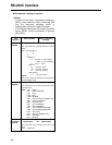
The VTR can be operated by commands when the
RS-232C interface is used. (Refer to the command
tables on page 125 and 126.)
∫
Condition for acknowledging
commands from RS-232C interface
Setup menu item No.204 (RS232C SEL): ON
If the above condition is not met,
[ACK]+[STX]ER001[EXT] is returned to the external
component. Whether [ACK] is returned depends on
the setting which has been selected for setup menu
item No.209 (RETURN ACK).
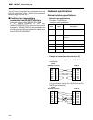
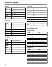
Hardware specifications
External interface specifications
RS-232C interface
•
Connector pin specifications
Connector: D-SUB 25-pin
(crossover cable supported)
Pin No. Signal Description
1 FG Protective ground (frame ground)
2 RXD Received data (data is sent to PC)
3 TXD Transmitted data (data is received
from PC)
4 CTS Clear to send (shorted with pin 5)
5 RTS Request to send (shorted with pin 4)
6 DTR Data terminal ready (no processing)
7 SG Signal ground
20 DSR Data set ready (+ voltage output after
communication enable status)
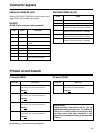
•
Example of connection with controller (PC)
(Using crossover cable with D-SUB 25-pin
connectors)
PC side
(D-SUB 25-pin connector)
VTR side
FG
TXD
RXD
RTS
CTS
DSR
SG
DTR
1
2
3
4
5
6
7
20
FG
RXD
TXD
CTS
RTS
DTR
SG
DSR
1
2
3
4
5
6
7
20
(Using crossover cable with D-SUB 9-pin and D-
SUB 25-pin connectors)
PC side
(D-SUB 9-pin connector)
VTR side
RXD
TXD
DTR
SG
DSR
RTS
CTS
2
3
4
5
6
7
8
FG
RXD
TXD
CTS
RTS
DTR
SG
DSR
1
2
3
4
5
6
7
20