


14
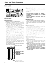
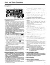
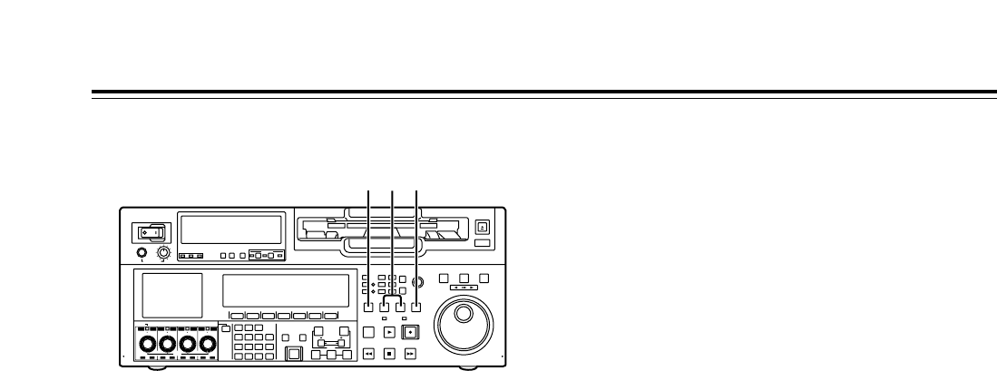
Front panel
Y
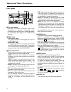
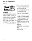
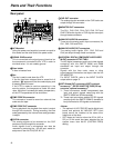
STANDBY button
The same tape tension is applied as in the regular
stop mode. While the head drum is rotating, the
button’s lamp lights to indicate that the standby ON
mode is now established.
If the button is pressed in the stop mode, the
standby OFF mode is established followed by the
half loading mode. At this time, its lamp goes off.
When the VTR is left in the stop mode beyond a
specific period of time, it is automatically set to the
standby OFF mode in order to protect the tape.
In the standby OFF mode, if this button or the
STOP button is pressed, the VTR is set to the
standby ON mode. If a button other than the
STOP button is pressed, the VTR is set to the
mode that corresponds to the button pressed.
The time taken by the VTR to transfer to the
standby OFF mode can be selected using a setup
menu item.
Parts and Their Functions
Z
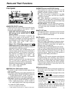
PLAYER and RECORDER buttons
These buttons are operated if the VTR is to be used
as a recorder to conduct editing operations with a
VTR equipped with an RS-422A serial interface
remote control connector (9 pins). Neither button
works when the VTR is used on its own.
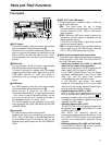
PLAYER: When this button is pressed, its lamp
lights to indicate that the player connected to the
VTR can be operated by remote control. The
VTR’s editing and tape transport system buttons
can now be used to control the player.
RECORDER: When this button is pressed, its lamp
lights to indicate that the editing and tape
transport system buttons can now be used to
operate the recorder (this VTR).
• When the PLAYER button or RECORDER button
is pressed while ENA has been selected as the
setup menu item No.200 (PARA RUN) setting,
the lamps of both buttons light to indicate that the
VTR now serves as the master unit for parallel
run operations. However, when this setting is
used, it is no longer possible to perform external
control from the REMOTE connector (9 pins).
[
INPUT CHECK button
Only while this button is held down are the input
signals from the monitor output connector output to
enable the input video and audio signals to be
monitored.
The time code generator can be checked on the
time code display.
Select LATCH as the setup menu item No.517
(TCG OUT) setting in order to continue displaying
the time code generator value even after the INPUT
CHECK button has been released.
<Note>
The INPUT CHECK function does not work for the
CUE signal and SDTI signals. Input signals can be
monitored in the E-E mode.
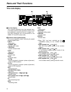
POWER
OFF
ON
HEADPHONES
PUSH
LOCK
FULL
CH CONDITION
MONITOR
FULL/FINE
REMOTE
LR
9P 50P
RS-232C
CH12345678
CUE
XL/L/M
-
cassette
Do not insert S-cassette
without adapter
EJECT
AUDIO CH SELECT
SHIFT
ABC DEF GHI
JKL MNO PQRS
PREVIEW/
REVIEW
PRE-
ROLL
A IN A OUT
HOME RF1 ASSEM
ADJUST
SHTL
REV FWD
VARJOG
STAND BY
RECORDER INPUT CHECK
PLAYER
SERVO
EDIT PLAY REC
REW STOP FF
REC INHIBIT
PUSH-INTER
INSERT
RF2
VIDEO
UNITY TC CUE
AUDIO
UNITY DIAG MENU
TRIM
SET
IN
OUT
AUTO
EDIT
789
456BS
TUV WXYZ
123
ENT
0CTF
F1 F2 F3 F4 F5 F6
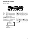
CH
1
CH
5
CH
2
CH
6
CH
3
CH
7
CH
4
CH
8
FULL
REC P8 REC P8 REC P8 REC P8
Y [Z