


73
Function menus
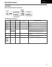
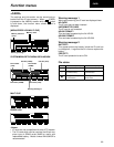
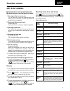
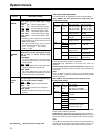
<50P IN/OUT ASSIGN>
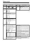
Press (RESET) while holding down the button.
All the registered item names and registered values
are now set to the factory settings. (These settings
cannot be restored.)
FF4
Registering functions in the input pins/Active inputs
Registering functions in the output pins/Active outputs
Clearing
Resetting all the items and values
1.
Selecting the 50-pin connector pins
Turn the ADJ dial to move the selection marker and
select the pin of the 50-pin connector into which the
menu item is to be registered.
2.
Entering the 50-pin connector pins
Press the ADJ dial.
The entered 50-pin connector pin display is highlighted.
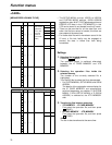
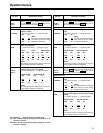
4.
Entering the menu item
Press the ADJ dial.
The on-screen setting display now blinks.
1.
Turn the ADJ dial to move the selection marker and select the
pin of the 50-pin connector whose menu item is to be cleared.
2.
Press (RESET). The registered item name
and registered value displays now go blank.
F4
3.
To clear the menu items in other 50-pin connector
pins, repeat steps 1 and 2.
3.
Selecting the menu item
Turn the ADJ dial and select the menu item for the pin
of the 50-pin connector which was selected in step 1
above.
5.
Selecting the setting
Turn the ADJ dial and select the setting for the
menu item which was selected in step 3 above.
6.
Entering the setting
Press the ADJ dial
.
What is to be operated by the ADJ dial returns to the
front panel. Whatever was selected in step 3 is
displayed as the registered item name and whatever was
selected in step 5 is displayed as the registered value.
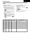
7.
To select menu items and settings for other 50-pin
connector pins, repeat steps 1 to 6.
8.
Saving the data in the 50-pin registration file
To save what has been set in the 50-pin connector in
the 50-pin registration file, press (SET).
If (EXIT) is pressed without the above settings
have been saved, those settings will be canceled.
F6
F5
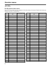
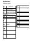
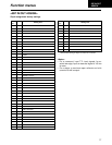
Special IN menu list
No.
SUPER
DISPLAY
Description of setting
B00
STBY ON
For transferring to the STANDBY ON mode.
B01
STBY OFF
For transferring to the STANDBY OFF mode.
B02
STBY ONOFF
For alternately transferring to the STANDBY ON
and OFF mode.
B03
EJECT
For transferring to the EJECT mode.
B04
CUE
For prerolling the tape to the IN point when the
IN point has been registered; for prerolling the
tape to the current point when the IN point has
not been registered.
B05
IN SET
For registering the edit IN point.
B06
STILL
For transferring to the still picture (STILL) mode.
B07
422 REM ON
The 9-pin connector functions.
B08
422 REM OFF
The 9-pin connector does not function.
B09
TC EXT
For returning TC SOURCE to the previous EXT
mode.
(No switching occurs if the EXT mode is
currently established
.)
B10
TC INT AUTO
For switching TC SOURCE to INT and TCG
MODE to AUTO.
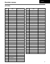
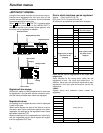
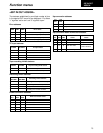
B20
PROTECT
HALF
For switching the tape protection mode operation to
half-loading in the event that the VTR has been left
standing in the STOP mode or the STILL mode while
any of the search modes (JOG, VAR or SHTL) was
established.
B21
PROTECT
T-REL
For switching the tape protection mode operation to
tension release when the VTR has been left standing
in the STOP mode or the STILL mode while any of the
search modes (JOG, VAR or SHTL) was established.
Functions not featured on the setup menua
SRC PROTECT and STOP PROTECT settings switched simultaneously
4.
To save what has been set in the 50-pin connector in
the 50-pin registration file, press (SET).
If (EXIT) is pressed without the above settings
have been saved, those settings will be canceled.
F6
F5
50P IN/OUT
ASSIGN
B11
TC EXT_L
REG
For switching TC SOURCE to EXT_L and TCG
MODE to REGEN.