


8
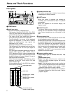
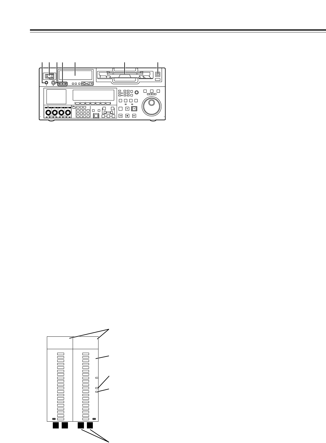
Front panel
1
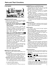
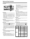
POWER switch
2
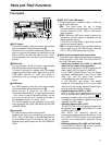
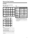
Audio level meter
The audio information is displayed here.
• The levels of the CH1, CH2, CH3, CH4, CH5,
CH6, CH7 and CH8 PCM audio signals and level
of the CUE track signal are displayed here.
• The levels of the input signals are displayed
during recording and when E-E is selected.
During playback, the levels of the playback
signals are displayed. In the INPUT CHECK
status, the levels of the input signals are
displayed for CH1 to CH8.
• Input signal display for each of the channels
The indicators for the selected input signals light.
(SDI lights when the SD SDI input signal is
selected.)
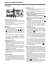
If an input signal has been selected but it has not
actually been input,the AES, HDSDI, SDI or
SDTI indicator will blink if a signal corresponding
to one of these indicators was selected whereas
the ANA indicator will remain lighted if it was an
ANA signal that was selected.
When the internal signal (INT SG) has been
selected, all the AES, ANA, HDSDI, SDI and
SDTI indicators light.
All the indicator are off in the 23/24 Hz mode or
25 Hz (HD or SD) mode.
3
Cassette insertion slot
If the slot’s orange plate is visible, it means that a
cassette tape is already inserted.
4
EJECT button
When this button is pressed, the cassette is
unloaded, and a few seconds later it is ejected
automatically.
When CTL appears on the counter display, the
display is reset.
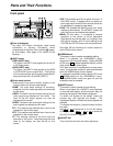
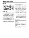
5
Headphones jack
The sound heard during recording, playback or
editing can be monitored through headphones
when stereo headphones are connected to this
jack.
6
Volume control dial
This control dial is used to adjust the volume level
of the headphones and monitor output.
Whether the volume level of the monitor output is to
be coupled together with that of the headphones to
this dial or separated can be selected using the
setup menu item No.712 (MONI OUT). (Note that
the volume level of the headphones is coupled at all
times.) When the volume levels have been
separated, the UNITY value (prescribed value)
applies to the monitor output.
7
Channel condition lamps
These lamps light to indicate the error rate
status.
(Green
“
amber
“
red)
Green: This lights when the error rates for the
video and audio playback signals are both at
acceptable levels.
Amber: This lights when the error rate for either the
video or audio playback signals has deteriorated.
The playback picture and sound remain
unaffected even while this lamp is lighted.
Red: This lights when correction or interpolation
has been engaged for either the video or audio
playback signals.
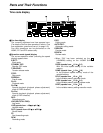
Parts and Their Functions
POWER
OFF
ON
HEADPHONES
PUSH
LOCK
FULL
CH CONDITION
MONITOR
FULL/FINE
REMOTE
LR
9P 50P
RS-232C
CH12345678
CUE
XL/L/M
-
cassette
Do not insert S-cassette
without adapter
EJECT
AUDIO CH SELECT
SHIFT
ABC DEF GHI
JKL MNO PQRS
PREVIEW/
REVIEW
PRE-
ROLL
A IN A OUT
HOME RF1 ASSEM
ADJUST
SHTL
REV FWD
VARJOG
STAND BY
RECORDER INPUT CHECK
PLAYER
SERVO
EDIT PLAY REC
REW STOP FF
REC INHIBIT
PUSH-INTER
INSERT
RF2
VIDEO
UNITY TC CUE
AUDIO
UNITY DIAG MENU
TRIM
SET
IN
OUT
AUTO
EDIT
789
456BS
TUV WXYZ
123
ENT
0CTF
F1 F2 F3 F4 F5 F6
CH
1
CH
5
CH
2
CH
6
CH
3
CH
7
CH
4
CH
8
FULL
REC P8 REC P8 REC P8 REC P8
1 65 2 3 47
0
-
4
-
8
-
12
-
16
-
20
-
25
-
30
-
40
- -
•4
dB
AES ANA
HD SDI SDTI
•3
•2
•1
0
-
1
-
2
-
3
-
4
L R
-
16
-
17
-
18
-
19
-
20
-
21
-
22
-
23
-
24
•16
dB
AES ANA
HD SDI SDTI
•12
•8
•4
0
-
5
-
10
-
20
L R
Reference level (
j
20 dB)
(AJ-HD1700P)
Left (L) and right (R)
monitor channel displays
Input signal display
Level meter
Reference level (
j
18 dB)
(AJ-HD1700E)