


8
9
Quick Start
Guide
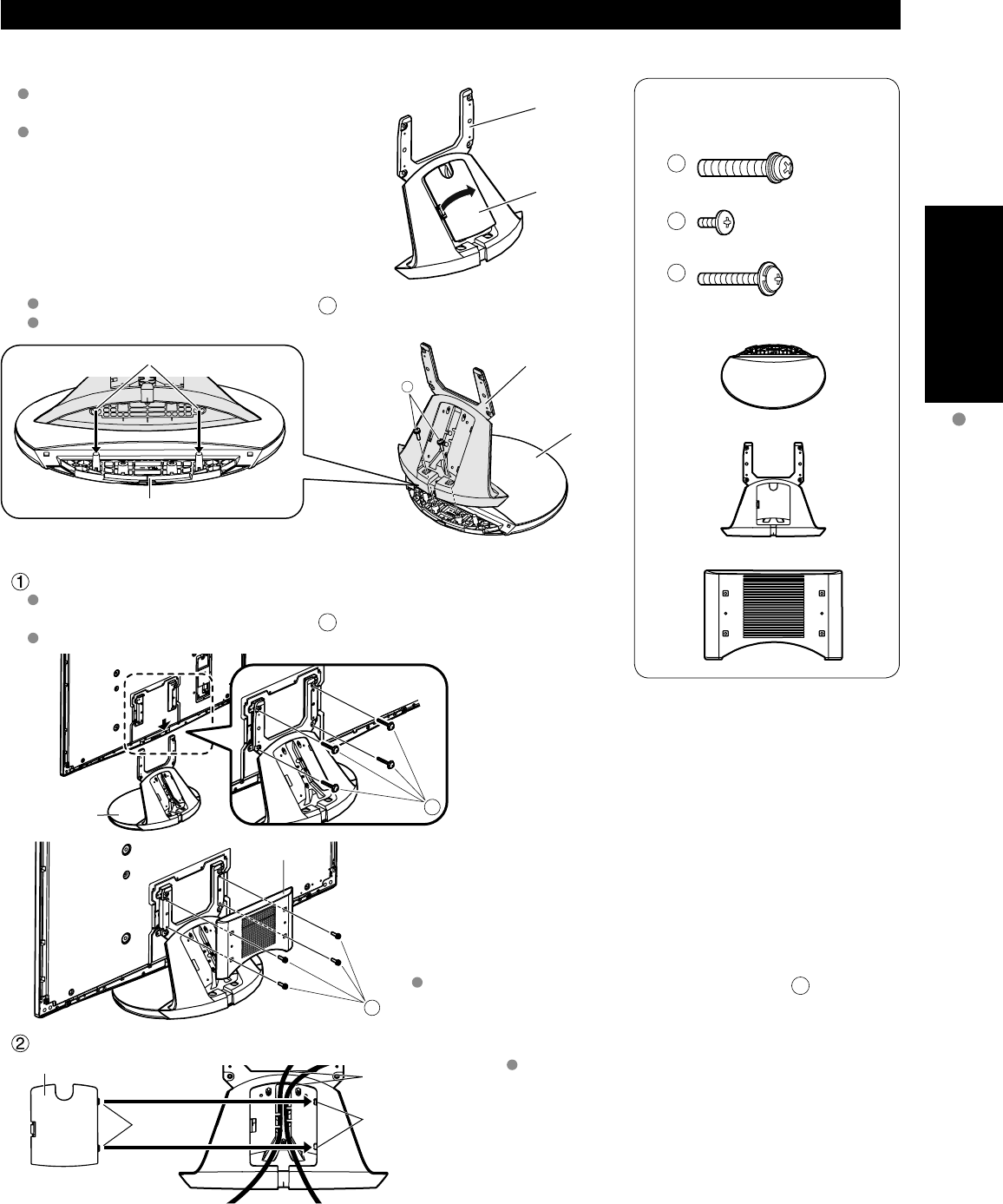
Accessories/Optional Accessory
Accessories
Assembly screws
A
M8 × 30 (Silver) (2)
B
M4 × 10 (Black) (4)
C
M5 × 25 (Black) (4)
Base (1)
Frame (1)
Holder cover (1)
V
I
E
R
A
C
A
S
T
V
I
E
R
A
T
O
O
L
S
V
I
E
R
A
L
i
n
k
Accessories/Optional Accessory
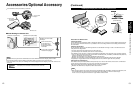
Accessories
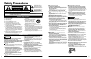
Check you have all the items shown.
Remote Control
Transmitter
N2QBYB000005
Batteries for the
Remote Control
Transmitter (2)
AA Battery
Pedestal
TBLX0107
Product Registration Card
(U.S.A.)
Customer Care Plan Card
(U.S.A.)
Operating Instructions
Viera Concierge and basic
instruction for HDTV
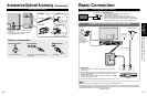
Installing the remote’s batteries
Pull open
Hook
Note the correct
polarity (+ or -).
Close
Caution
Incorrect installation may cause battery
leakage and corrosion, resulting in
damage to the remote control.
•
Do not mix old and new batteries.
•
Do not mix different battery types
(such as alkaline and manganese
batteries).
•
Do not use rechargeable (Ni-Cd)
batteries.
Do not burn or break batteries.
Do not disassemble or modify the
remote control.
Optional Accessory
Note
In order to maintain the TV’s performance and safety, be absolutely sure
to ask your dealer or a licensed contractor to secure the wall-hanging
brackets.
Carefully read the instructions accompanying the plasma TV stand or
pedestal, and be absolutely sure to take steps to prevent the TV from
tipping over.
Handle the TV carefully during installation since subjecting it to impact
or other forces may cause its panel to crack.
Wall-hanging bracket
(vertical)
TY-WK5P1SW
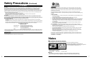
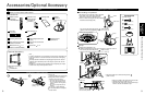
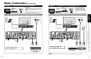
Attaching the pedestal to TV
■
Assembling the pedestal
Be careful not to scratch the surface (part with
gloss finish) of the base during assembly
Remove the cable cover attached to the
frame. (It will be used again after the pedestal
is attached to the display Unit.)
Frame
Cable cover
Fix securely with assembly screws
A
. (Total 2 screws)
Tighten screws firmly (tightening torque: 1.8 - 2.0 N• m)
A
Hole for the base installation
Base
Frame
Base
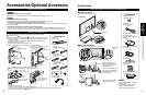
■
Set-up
Attach the pedestal to TV
Slide the pedestal frame posts into the brackets on the back of the TV.
Fix securely with assembly screws
C
. (Total 4 screws)
Tighten screws firmly (tightening torque: 1.5 - 1.8 N• m)
C
Pedestal
B
Holder cover
Attach the Holder cover with assembly screws
B
.
(Total 4 screws)
Attach the cable cover
Cable cover
Cable
Hole
Tabs
Insert the tabs of the
cable cover into the hole at
the back of the pedestal.
Place each cable in the groove at the back of the
pedestal and snap the cable cover in.
* The lower part of the groove is separated in right
and left. Use the one suitable for you.
Accessories
How to assemble
(p. 9)
Cleaning cloth
RS232C terminal
Specifications
Wireless Unit set
p. 11
(Receiver and Transmitter)
Tuner Box
TU-Z100U
Cable clamper (2)
Speaker set
p. 10