


41
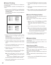
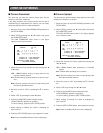
■ Cable Compensation/VD2/Data
This item lets you select the optimum setting for the cable-
loss compensator and whether to supply the VD2 (sync)
signal or control data to the camera.
Note: These settings will work only for the input channels
that have the multiplex feature with the Data Multiplex
Board WV-BP6164 installed. The boards are installed
for input channels 1 through 4 at the factory. You can
install boards for other channels. For installations, see
page 12.
1. Press the [FUNCTION] button while the SYSTEMSETUP
menu (1 of 2) is displayed on the monitor screen.
The next page of the menu appears on the screen.
2. Move the cursor to CABLE COMP/VD2/DATA SETUP in
the SYSTEM MENU, then press the [HOME/SET] button.
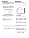
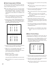
The CABLE COMP/VD2/DATA SETUP table shown in
the figure appears on the monitor screen.
3. Move the cursor to the columns you want to edit for the
channel by pressing the C, D, A or B button.
4. Select one of the parameters shown below in the
CABLE column by pressing the - or + button.
This item lets you select a suitable cable-loss compen-
sator corresponding with the cable length.
S: Up to 400 m (1 300 ft)
M: 400 m (1 300 ft) to 700 m (2 300 ft)
L: 700 m (2 300 ft) to 900 m (3 000 ft)
(Using the RG-59/U, BELDEN 9259 or equivalent cable)
Note: Set CABLE to S if no camera is connected to the
channel.
5. Select either ON or OFF in the VD2 column by pressing
the - or + button.
Note: Select ON for a camera with VD2 capability, oth-
erwise select OFF.
6. Select one of the parameters shown below in the DATA
column by pressing the - or + button.
ON: Communicates with the camera site by multiplexed
data.
1-16: Communicate with the camera site by RS-485.
This number indicates the unit address of the
selected camera.
OFF: Disables communication with the camera site.
6. Repeat steps 3 to 6 above to edit other channels.
Press the [FUNCTION] button to display the next page
of the table, then press this button again to return to the
previous page.
7. After finishing the settings, press the [SET UP/ESC] but-
ton to execute the settings and returns to the previous
SYSTEM SETUP menu.
Note: Installation of the WV-PB6164 Data Multiplex
Boards is required for controlling more than 4 cam-
eras.
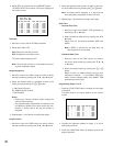
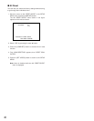
■ Alarm Terminal Setup
This item lets you designate the alarm input from the
ALARM/REMOTE port located on the rear of the multiplexer.
1. Move the cursor to ALM TERMINAL SETUP in the SYS-
TEM SETUP menu, then press the [HOME/SET] button.
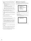
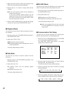
The ALARM TERMINAL SETUP table shown in the fig-
ure appears on the monitor screen.
2. Move the cursor to the columns you want to edit for the
terminal number by pressing the C, D, A or B button.
3. Select the channel number to be assigned in the CAM
column by pressing the - or + button.
Note: Channel numbers can also be input directly with
the camera number buttons.
ALARM TERMINAL SETUP
NO. CAM PRE NO. CAM PRE
1 1CH - 9 9CH -
2 2CH - 10 10CH -
3 3CH - 11 11CH -
4 4CH - 12 12CH -
5 5CH - 13 13CH -
6 6CH - 14 14CH -
7 7CH - 15 15CH -
8 8CH - 16 16CH -
CABLE COMP/VD2/DATA SETUP 1 OF 2
CAM CABLE VD2 DATA
1CH S ON ON
2CH S ON ON
3CH S ON ON
4CH S ON ON
5CH S OFF OFF
6CH S OFF OFF
7CH S OFF OFF
8CH S OFF OFF
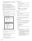
CABLE COMP/VD2/DATA SETUP 2 OF 2
CAM CABLE VD2 DATA
9CH S OFF OFF
10CH S OFF OFF
11CH S OFF OFF
12CH S OFF OFF
13CH S OFF OFF
14CH S OFF OFF
15CH S OFF OFF
16CH S OFF OFF