


69
■ Installations
The installations described below should be made by
qualified service personnel or system installers.
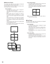
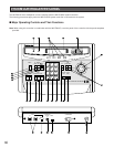
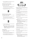
● Modifying the Front Panel
Peel the tape off the supplied panel templates, then attach
them on the front panel of the system controller.
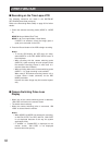
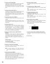
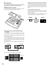
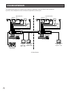
● Connection with the WV-CU550C System
Controller
If the supplied 6-conductor cable assembly is used, simply
plug one end of the cable into the DATA IN port of the
video multiplexer and the other end into the DATA OUT port
on the system controller.
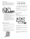
If you use cables assembled from locally procured materi-
als, it is important that only high quality, data grade cable,
suitable for RS-485 communication (shielded 4-wire twisted
pair cable) is used.
Low grade cable will result in unstable operation of the sys-
tem.
Connection with the WV-CU550C System Controller
TERM. MODE
ON OFF
0
OFF
ON
TERM.
OFF
INOUT
ON
DATA
IN OUT
TERM
ON OFF
DATA
0
1
2
3
4
5
6
7
8
9
CONTROLLER
UNIT NO.
1-8
Video Multiplexer
WJ-FS616C
System Controller
WV-CU550C
1
6
1
6
No. No.
Name
Data Flow
1 1
GND
–
2 2
RX(B)
FS616C ← Controller
3 3
RX(A)
FS616C ← Controller
4 4
TX(B)
FS616C → Controller
5 5
TX(A)
FS616C → Controller
6 6
GND
–
Controller end
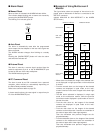
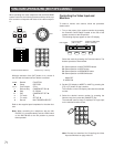
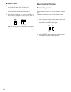
• Setting the Termination and Controller Unit Number
The Termination switch and the Controller Unit Number
switch are located on the rear of the system controller.
When combined with the WJ-FS616C video multiplexer,
always keep these switches in the positions shown
below.
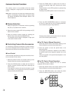
• Setting the Mode Selection Switch
The Mode Selection switch, that selects the operation
mode of the system controller, is located on the rear of
the system controller.
When combined with the video multiplexer, always
keep these switches in the positions shown below.