C242M-C (11/99)
MM3000
Monitor Mount
®
IMPORTANT SAFEGUARDS AND WARNINGS
Prior to installation and use of this product, the following WARNINGS should be observed.
1. Installation and servicing should only be done by qualified service personnel and conform
to all local codes.
2. Unless the unit is specifically marked as a NEMA Type 3, 3R, 3S, 4, 4X ,6 or 6P enclo-
sure, it is designed for indoor use only and it must not be installed where exposed to rain
and moisture.
3. Use only installation methods and materials capable of supporting four times the maxi-
mum specified load.
4. Only use replacement parts recommended by Pelco.
Please thoroughly familiarize yourself with the information in this manual prior to installation
and operation.
3500 Pelco Way,
Clovis, CA 93612-5699
USA
In North America & Canada:
Tel (800) 289-9100
FAX (800) 289-9150
International Customers:
Tel +1 (559) 292-1981
FAX +1 (559) 348-1120
www.pelco.com
LISTED
U
L
®
DESCRIPTION
The MM3000 is a ceiling “J” mount designed for use with 9-inch (22.86 cm) and 12-inch (30.48
cm) CCTV monitors. The mount allows horizontal and vertical adjustment of the monitor.
NOTE:
The two fasteners re-
quired to secure the MM3000 to
the mounting surface (minimum
1/4-inch diameter recom-
mended) and screws to mount
the monitor are not supplied;
screws holding feet on bottom of
monitor may be used to secure
monitor to mount.
INSTALLATION
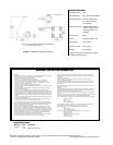
To install the MM3000, perform the following steps.
1. Drill holes in the mounting surface using the mount as a template and attach the mount
securely with fasteners of a suitable size.
2. Remove the rubber feet from the bottom of the monitor. Place the monitor on the monitor
support pan and secure the monitor to the pan. (The screws previously used to secure
the rubber feet to the bottom of the monitor may be used.)
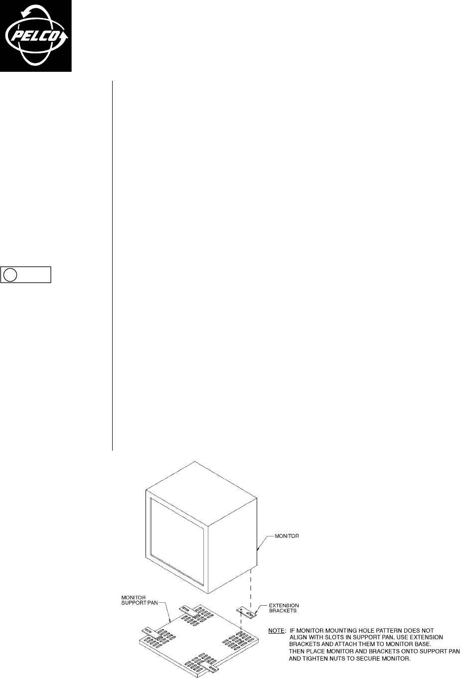
3. If the monitor mounting hole pattern does not align with slots in support pan, use exten-
sion brackets provided and attach them to monitor base (see Figure 1). Then place moni-
tor and brackets onto support pan and tighten nuts (provided) to secure monitor.
4. Adjust pan rotation (360°) and tilt angle of monitor support pan (45° down). Lock into po-
sition by tightening the hex head bolts.
Figure 1. Attaching Support Pan Extension Brackets