


C1919M-D (3/02)
PV130 RS-232/422 Converter Kit
Installation Instructions
®
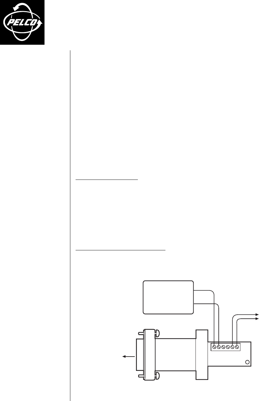
Figure 1. Connection Diagram
3500 Pelco Way,
Clovis, CA 93612-5699
USA
In North America & Canada:
Tel (800) 289-9100
FAX (800) 289-9150
DataFAX (800) 289-9108
International Customers:
Tel +1(559) 292-1981
FAX +1(559) 348-1120
DataFAX +1(559) 292-0435
PelcoEurope BV
Dillenburg Center
Dillenburgstraat 5F
5652 AM Eindhoven
The Netherlands
Tel +31(40) 251-9870
FAX +31(40) 251-9835
Pelco Online
www.pelco.com
*12 VDC POWER SUPPLY
*IF NECESSARY
GND
+12 VDC
PV130 CONVERTER
TO RECEIVER(S)
RX +
RX -
TX-
TX+
RX-
RX+
GND
+12 VDC
FEMALE DB9 TO
TRANSMITTER
COM 2 PORT
DESCRIPTION
The PV130 RS-232/422 Converter Kit provides a bi-directional electrical interface between RS-
232 and RS-422 data ports. This allows any application that requires an RS-232 device to con-
nect to an RS-422 or RS-485 port on Pelco products. RS-422 and R-485 ports are found on
Pelco switchers, multiplexers, keyboards, and camera control receivers.
For example, you can connect a PelcoNet transmitter/receiver to a Spectra II, KBD300, Genex
Multiplexer, or CM9760-CC1 using a PV130.
The power supply allows the PV130 to communicate serial port data over wire pairs for dis-
tances up to 4,000 feet (1,219 m) on the RS-422 side.
You must supply all necessary cables between the converter and the receivers.
INSTALLATION
Package Contents:
• RS-232/422 Converter
• 12 VDC Power Supply, 1.2W
Control Connections
1. Connect the 9-pin DB9 side of the converter to the COM port on the receiver or transmitter.
2. Wire the receiver’s RX- and RX+ terminals to the converter’s TX- and TX+ terminals. Use a
120-ohm resistor, if necessary, to terminate the line at the receiver’s RX- and RX+ terminals.
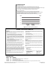
NOTE:
Proper operation of an RS-422 circuit requires that the active devices at both
ends of the communications facility be referenced to a common ground, such as earth. If
the ground is established through a metallic conductor, we recommend that 100-ohm resis-
tors be placed in series with the ground connection at each end (refer to Figure 2). This
limits any currents that can be caused by other ground paths.
Connecting the Power Supply
1. Connect the black/white stripe wire to the converter’s +12 VDC terminal and the solid black
wire to the GND terminal.
2. Plug the power supply into a 115 VAC wall outlet or power strip.