


6
T
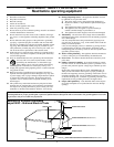
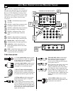
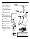
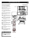
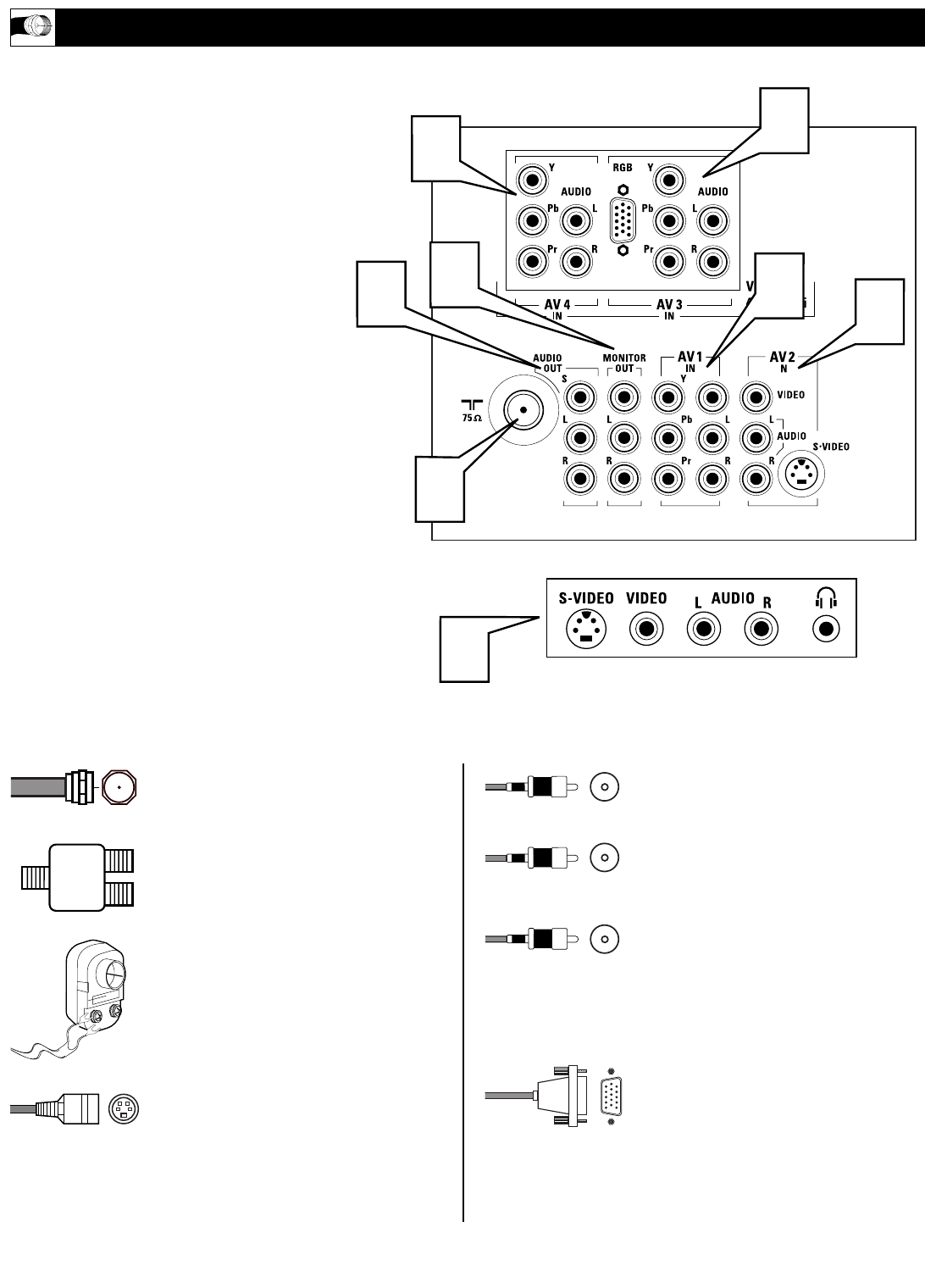
he television is equipped with external
input and output jacks for use with optional
accessory devices such as Home entertainment
Receivers, VCRs, DVD Player, Gaming Units,
Video Cameras, etc. The following gives a brief
explanation of the different types of jacks avail-
able and the type of cables needed to make
connections.
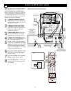
1
75Ω RF - Cable/Antenna Input connec-
tion jack.
2
AV 1 IN - Audio/Video connection jacks
including Component Video Inputs.
3
AV 2 IN - Audio/Video Input connection
jacks including S-Video connections.
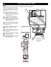
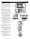
4
AV 3 IN - Component Video, VGA
(RGB), and Audio Input connection
jacks.
5
AV 4 IN - High Definition Component
Video and Audio Input connection jacks.
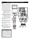
6
Monitor Out - Audio/Video Output
connection jacks (TV tuner signal only).
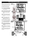
7
Audio Out - Audio connections for
home entertainment receivers and exter-
nal speakers.
8
SIDE - Audio/Video Input jacks include
a S-Video jack, plus a Headphone jack
located on the side of the cabinet.
JACK P
ANEL DESCRIPTIONS AND REQUIRED CABLES
1
2
8
3
4
5
6
Located on the back of the TV
Located on the side of the TV
7
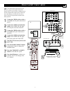
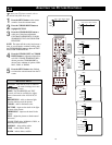
A 75-ohm coaxial cable connects signals
from an antenna or a cable TV company
to the antenna jack on the back of the TV.
Coaxial cables use “F” connectors.
A two-way signal splitter enables you to
take a single antenna or cable TV signal
and supply it to two different inputs.
A 300- to 75-ohm twin-lead adapter
accepts the antenna cables (called twin-
lead wires) from an antenna, allowing you
to connect the antenna signal to the TV.
A S-Video cable provides better picture
performance than regular (composite)
video connections.
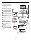
S-Video cables can be used only with S-
Video-compatible accessory devices. You
must also connect the left and right audio
cables to the AV 2 Audio in jacks because
the S-Video jack carries only the picture
signal, not the sound.
Video and audio cables with standard
RCA (phono) connectors connect the
video and audio jacks of accessory
devices such as VCRs and DVD players
to the jacks on the TV.
These connectors are usually color coded.
The jacks on your TV are also color
coded to match the colors of the connec-
tors. Yellow for video (composite) and
Red and White for the right and left audio
channels. The video cables used to con-
nect component video or RGB (high-reso-
lution) jacks are color coded red, green,
and blue.
A VGA (HD15) cable makes a VGA
(RGB) connection to the HD INPUT-AV
4 jack on the rear of the TV.
Cable Descriptions:
Yellow - Video
White - Audio Left
Red - Audio Right