


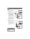
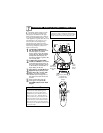

COMPONENT VIDEO
(CVI) INPUT C
ONNECTIONS
C
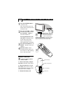
omponent Video inputs provide
for the highest possible color
and picture resolution in the play-
back of digital signal source materi-
al, such as with DVD players. The
color difference signals (Pb, Pr) and
the luminance (Y) signal are con-
nected and received separately,
which allows for improved color
bandwidth information (not possible
when using composite video or S-
Video connections).
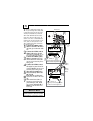
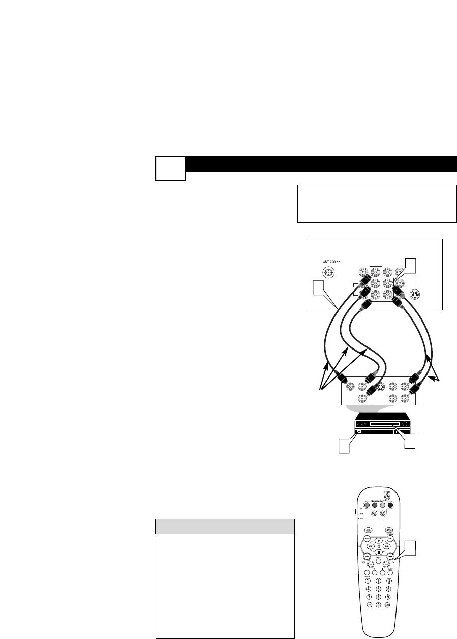
1
Connect the Component (Y,
Pb, Pr) Video OUT jacks from
the DVD player (or similar
device) to the (Y, Pb, Pr) in(put)
jack on the TV. When using the
Component Video Inputs, it is
best not to connect a signal to the
AV in Video Jack.
2
Connect the red and white
AUDIO CABLES to the Audio
(left and right) output jacks on
the rear of the accessory device
to the Audio (L and R) AV1 in
Input Jacks on the TV.
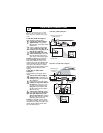
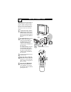
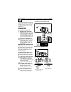
3
Turn the TV and the DVD (or
digital accessory device) ON.
4
Press the CH + or CH – but-
tons to scroll the available
channels until CVI appears in
the upper left corner of the TV
screen.
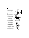
5
Insert a DVD disc into the
DVD player and press the
PLAY ᮣ button on the DVD
Player.
The description for the component video
connectors may differ depending on the
DVD player or accessory digital source
equipment used (for example, Y, Pb, Pr; Y,
B-Y, R-Y; Y, Cr, Cb). Although abbrevia-
tions and terms may vary, the letters b and r
stand for the blue and red color component
signal connectors, and Y indicates the lumi-
nance signal. Refer to your DVD or digital
accessory owner’s manual for definitions and
connection details.
HELPFUL
HINT
VOL
4
L/Mono
Monitor out
VIDEO
S-VIDEO
AV1 in
Y
Pb
Pr
AV2 in
AUDIO
R
COMPONENT VIDEO INPUT
S-VIDEO
OUT
OUT
OUT
L
R
AUDIO
VIDEO
COMP VIDEO
Y
Pb
Pr
2
1
3
5
Component
Video Cables
(Green, Blue,
Red)
Audio
Cables
(Red &
White)
Accessory Device
Equipped with
Component Video
Outputs
Back of TV
The CVI connection will be dominate over the AV1
in Video Input. When a Component Video Device is
connected as described, it is best not to have a video
signal connected to the AV1 in Video Input jack.
7