


English
20
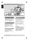
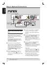
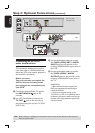
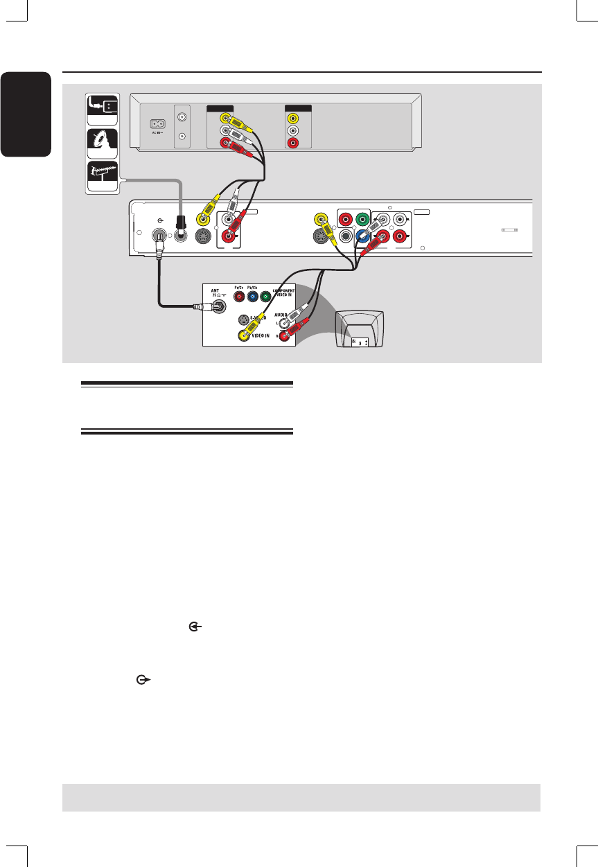
Step 2: Optional Connections (continued)
R
L
Y
P
B
P
R
VIDEO (CVBS)
COMPONENT
VIDEO
EXT 2
S-VIDEO (Y/C)
VIDEO (CVBS)
S-VIDEO (Y/C)
AUDIO
COAXIAL
R
L
R
L
(DIGITAL AUDIO)
INPUT
OUTPUT
EXT 1
AUDIO
TV-OUT
ANTENNA-IN
AUDIO
OUT
S-VIDEO
IN
VIDEO IN
TV
CABLE
SATELLITE
ANTENNA
VIDEO
IN
O
U
T
I
N
AUDIO
L
AUDIO
R
VIDEO
OUT
AUDIO
L
AUDIO
R
VHF/UHF
RF IN
VHF/UHF
RF OUT
A
B
C
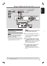
Rear of a VCR
(Example only)
D
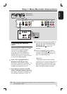
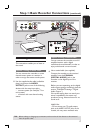
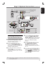
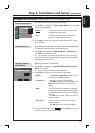
Connecting to a VCR or
other similar device
This connection enables you to record
from video tape to a DVD±R/±RW and
allows the VCR to be used for playback if
the recorder is turned off.
Before you start...
Your new recorder can replace the
VCR for all your recording needs.
Just unplug all the connections from
your VCR.
A
Connect the Antenna/Cable TV signal to
the ANTENNA-IN jack on the
recorder.
B
Use a RF coaxial cable to connect the
TV-OUT jack on the recorder to
the antenna input jack on your TV (VHF/
UHF RF IN.)
C
Use the audio/video cables to connect
the VIDEO (CVBS) EXT1/ AUDIO
INPUT jacks on the recorder to the
matching VIDEO/AUDIO output jacks on
the VCR.
D
Use the audio/video cables to connect
the VIDEO (CVBS) / AUDIO
OUTPUT jacks on the recorder to the
matching VIDEO/AUDIO input jacks on
the TV.
Helpful Hints:
– Most commercial video cassettes and
DVDs are copy-protected and therefore
cannot be recorded.
– Connect the recorder directly to the
TV. If there is a VCR or an additional device
in between, the picture quality may be poor
because of the copy protection system built
into the recorder.
TIPS: Before making or changing any connections, make sure that all the devices are disconnected
from the power outlet.