


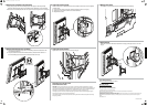
1 Install the TV brackets
Option 1: Installing for a at mounting surface
1 Align the TV brackets (A and B) with the screw holes on the back of the TV.
2 Place the M4/M5 washers (H) or M6/M8 washers (O) over the holes in the TV brackets that
align with the screw holes on the back of the TV, then insert the M4 screws (F), M5 screws (J),
M6 screws (L or M), or M8 screws (Q) through the washers.
3 Tighten the screws until they are snug against the TV bracket. Do not over tighten.
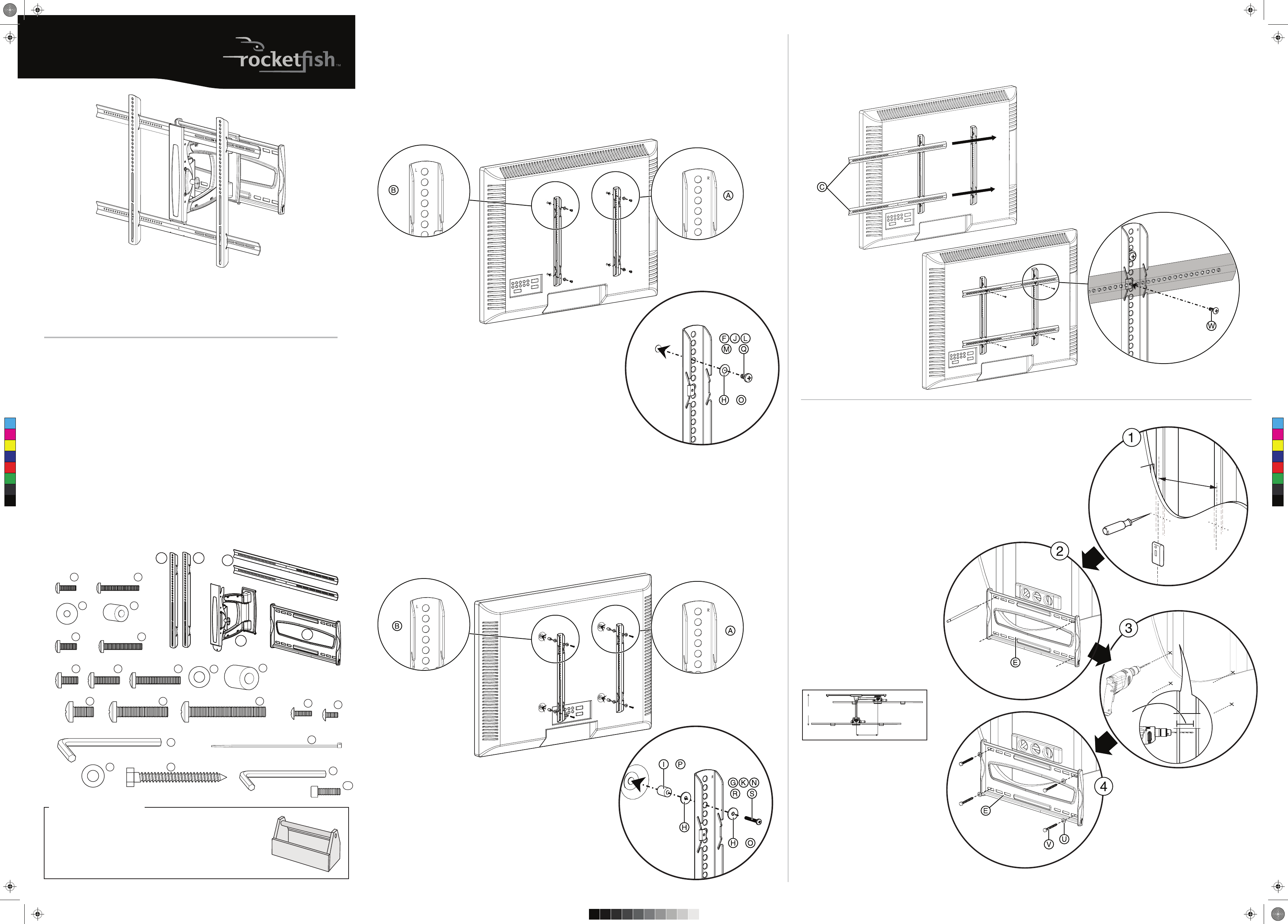
2 Add the horizontal bars
1 Slide the horizontal bars (C) through the wire guides on the TV brackets.
2 Secure the bars to the TV brackets using the 9/16 in. × 8/32 in. Phillips head screws (W).
Option 2: Installing for an obstructed mounting surface
Note: Use additional washers (H) with M4/M5 hardware only.
1 Place the M4/M5 spacers (I) or M6/M8 spacers (P) and the M4/M5 washers (H) into the
recessed screw holes on the back of the TV.
2 Align the TV brackets (A and B) with the spacers and washers on the back of the TV.
3 Place the M4/M5 washers (H) or M6/M8 washers (O) over the holes in the TV brackets that
align with the screw holes on the back of the TV, then insert the M4 screws (G), M5 screws (K),
M6 screws (N), or M8 screws (R or S) through the washers.
4 Tighten the screws until they are snug against the TV bracket. Do not over tighten.
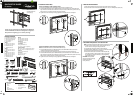
QUICK SETUP GUIDE
RF-TVMFM03
Tools you will need:
• Stud nder
• Awl
• Pencil
• Level
• Tape measure
• Phillips screwdriver
• Socket wrench with
1/2 in. socket or
adjustable wrench
• 7/32 in. wood drill bit
• Power drill
Package contents
A Right vertical TV bracket (1)
B Left vertical TV bracket (1)
C Horizontal TV bracket (2)
D Arm assembly (1)
E Wall plate (1)
M4 bag
F M4 × 12 mm screws (4)
G M4 × 30 mm screws (4)
H M4/M5 washers (8)
I M4/M5 spacers (4)
M5 bag
J M5 × 12 mm screws (4)
K M5 × 30 mm screws (4)
M6 bag
L M6 × 12 mm screws (4)
M M6 × 20 mm screws (4)
N M6 × 35 mm screws (4)
O M6/M8 washers (4)
P M6/M8 spacers (4)
Thank you for choosing the Rocketsh RF-TVMFM03.
The RF-TVMFM03 TV mount is designed to support a
at-panel TV weighing up to 130 lbs. (58.9 kg).
M8 bag
Q M8 × 16 mm screws (4)
R M8 × 40 mm screws (4)
S M8 × 60 mm screws (4)
Hex key bag
T 3/16 in. hex key (1)
Lag bolt bag
U Lag bolt washer (4)
V 5/16 in. × 2-3/4 in. lag bolt (4)
Bracket hardware
W 9/16 in. × 8/32 in. Phillips head screw (4)
X 3/8 in. × 8/32 in. Phillips head screw (1)
Cable ties
Y 8 in. nylon cable ties (5)
Cap screws
Z 5/32 in. hex key (1)
AA Cap screws (2)
A B
C
D
E
M4 bag
Cap screws with hex key
M5 bag
M6 bag
Bracket hardware
M8 bag
Hex key bag
Cable ties
Lag bolt bag
M4 × 12 mm
F
M4 × 30 mm
G
M5 × 12 mm
J K
M8 × 16 mm
Q
M8 × 40 mm
R
M8 × 60 mm
S
M6/M8
P
M4/M5
I
M6/M8
O
M4/M5
H
T
Y
M6 × 12 mm
L
M6 × 20 mm
M
M6 × 35 mm
N
W
X
AA
VU
Z
M5 × 30 mm
5/32 in.
5/16 in. × 2-3/4 in.
3/16 in.
3 Install the wall plate to a wood stud wall
Note: Any material covering the wall must not exceed 5/8 in. (16 mm).
1 Locate the studs. Verify the center of the stud with an awl
or thin nail or use an edge-to-edge stud nder.
2 Level the wall plate (E) and mark the hole locations.
3 Drill pilot hole to a depth of 3 in. using a 7/32 in. diameter drill bit.
4 Align the wall plate (E) with the pilot holes.
5 Place the washers (U) over the holes in the wall plate (E),
insert the lag bolts (V) through the washers, then tighten
the lag bolts only until the washers (U) are pulled rmly
against the wall plate.
CAUTION: Avoid potential
injuries or property damage!
DO NOT over-tighten
the lag bolts (V).
10-1/5 in.
7 in.
TV shifts 7 in. from the home position to
full extension.
16 in.
<5/8 in.
Note: Intended for use on
wood stud walls with 16 in.
or less spacing only.
R
or
or
or
or
or
(75 mm)
3 in.
Wall
TV
C
M
Y
CM
MY
CY
CMY
K
RF-TVMFM03_10-0726_QSG_V2_EN.eps 1 7/2/2010 1:18:59 PMRF-TVMFM03_10-0726_QSG_V2_EN.eps 1 7/2/2010 1:18:59 PM
V2
FINAL
FOR PRINT