


70 Chapter 4 Time Data and Sub LCD Menu
Chapter 4 Time Data and Sub LCD Menu
Input and Output Settings for Video and Audio
Signals –– Sub LCD Menu
Using the sub LCD menu, you can make settings
related to the input and output of video and audio
signals.
For more information about basic sub LCD menu
operations, see section “Sub LCD Menu Basic Operations
(see page 68)”.
Making Settings in the Audio
Settings Pages
For audio settings, use the audio settings pages of the
sub LCD menu.
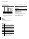
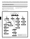
The audio settings pages are divided into four groups,
AU-1 to AU-4. Using these four groups of audio
settings pages, you can make four different sets of
audio settings. To call up one of the settings pages in a
group, select the group from the home page.
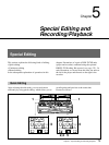
Each settings page has a number that indicates its
group and its position within the group. For example,
audio settings page 1-1 is the first page in group AU-1.
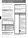
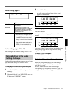
Audio settings page 1-1
Item Setting
AGC Turn the audio input AGC circuits ON and
OFF (enabled when the AUDIO INPUT
PRESET/VARIABLE switch of the control
panel is set to PRESET).
LIMITER Turn the audio input limiter circuits ON and
OFF (enabled when the AUDIO INPUT
PRESET/VARIABLE switch of the control
panel is set to VARIABLE).
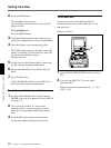
To switch to audio settings page 1-2
Press the PAGE button.
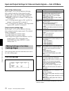
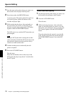
Audio settings page 1-2
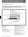
Audio settings page 1-2 displayed differs between
when the optional DSBK-140/150/160 board is
installed and when it is not installed.
Item Setting
MIX/SWAP CH 1 to 4 Select up to two audio input
signals (IN-1 to IN-4) to be
assigned to channels 1 to 4. When
two signals are selected, they are
mixed.
To select
1 Select the desired channel using
operation buttons F1 to F4.
2 Press the same operation button
as used in 1 repeatedly until the
input signal indication (IN-1/IN-
2/IN-3/IN-4) corresponding to
the desired signal is
highlighted.
3 With the input signal indication
for the selected signal
highlighted, press either the UP
button or the DOWN button so
that an asterisk (*) is added to
the highlighted input signal
indication.
4 To select the second input signal
for the same channel, repeat
steps 2 and 3.
To cancel the selection
Proceed as above to highlight the
desired input signal indication,
then press either the UP button or
the DOWN button so that the
asterisk preceding the highlighted
input signal indication disappears.
Note
When analog audio (ANALOG)
has been selected for input,
selecting IN-3 or IN-4 as the audio
input signal results in mute audio.
To switch to audio settings page 1-3
Press the PAGE button.
AGC
OFF
LIMITER
OFF
[AU-1-1]
MIX/SWAP
1*IN-1
IN-2
IN-3
IN-4
[AU-1-2]
2 IN-1
*IN-2
IN-3
IN-4
3 IN-1
IN-2
*IN-3
IN-4
4 IN-1
IN-2
IN-3
*IN-4
CH
MIX/SWAP
1*IN-1
IN-2
[AU-1-2]
2 IN-1
*IN-2
3*IN-1
IN-2
4 IN-1
*IN-2
CH
Display when the optional DSBK-140/150/
160 board is installed
Display when the optional DSBK-140/150/
160 board is not installed