


28
Setting the Time Data
Displaying Time Data and Operation
Mode Indications
Time data and operation mode indications can be
displayed on the monitor screen.
Time data can also be displayed in the time counter display
on this unit.
To view time data and operation mode
indications on the monitor screen
Set the CHARA. DISPLAY menu item (see page 66) to
ON (factory default setting).
The time data and the indication of the current operation
mode are superimposed on the video signal that is being
output from the SUPER connector, and can be viewed on
the monitor screen.
Use the DISPLAY CONTROL menu items (see page 66)
to select the information displayed and the character type
and position of the indications.
When you set the SUB STATUS menu item (see page 67)
to other than OFF, you can also display supplementary
status information on the monitor screen such as the
operating mode of the internal time code generator.
For details of supplementary status information, see
“Displaying Supplementary Status Information” on page
79.
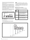
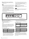
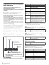
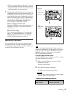
Monitor screen contents
The contents of the monitor screen are shown below.
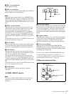
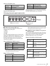
A Time data type
The following time data type indications are displayed.
a) You can switch between TC and VITC using the TC SELECT menu item
(see page 68).
b) “*” is displayed when data cannot be read in correctly.
B Drop frame indication for time code reader (on
DSR-DR1000 only)
C Drop frame indication for time code generator
(for DSR-DR1000 only)
D VITC field indication
E DSR-DR1000/DR1000P operation mode
TCR
PLA
Y
00:04 47
.
07*
.
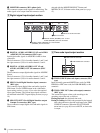
B Drop frame indication
for time code reader
a)
C Drop frame indication for
time code generator
a)
a) This character (.) can appear on the DSR-DR1000 only. The
character to appear in these two columns is always a colon
( : ) on the DSR-DR1000P.
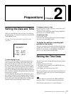
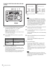
Time data
A Time data type
E DSR-DR1000/DR1000P operation mode
D VITC field
indication
F Recording indications during
simultaneous playback and recording
Indication Description
CNT Count value of the time counter
TCR Time code data from time code reader
(factory default setting)
UBR User bit data from time code reader
TCR.
Time code data from VITC reader
a)
UBR.
User bit data from VITC reader
a)
TCG Time code data from time code generator
UBG User bit data from time code generator
T*R
b)
Time code data from time code reader. The
asterisk indicates an interpolation by the time
code reader to make up for the time code
data not correctly read from the disk.
U*R
b)
User bit data from the time code reader. The
asterisk indicates that last data is retained by
the time code reader, as the new data has
not been read correctly from the disk.
. Drop frame mode (factory default setting)
: Non-drop frame mode
. Drop frame mode (factory default setting)
: Non-drop frame mode
(blank) Display fields 1 and 3.
* Display fields 2 and 4.
Display Operation mode
STOP Stop mode
F. FWD Fast forward mode
REW Rewind mode
PREROLL Preroll mode
PLAY Playback mode (servo unlocked)
PLAY-PAUSE Temporary stop of playback
PLAY LOCK Playback mode (servo locked)
REC Record mode (servo unlocked)