


34
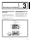
Recording
When controlling this unit from an editing control unit
connected to the REMOTE IN (R)connector, see “Control
mode selector” on page 15 and the description of the
REMOTE I/F menu item on page 72.
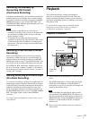
1
Power on the video monitor, then set its input
switches according to the signals input from the
player.
2
Set up the player to play back a tape.
For details, refer to the operating instructions for the
player.
3
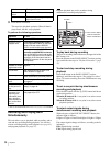
Power on this unit by pressing the 1 switch on the
front panel.
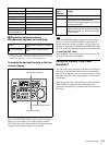
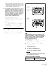
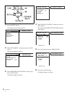
4
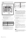
When the REMOTE indicator is off (the external
editing control unit is not used), use the COUNTER
SELECT button to select the type of time data to be
used.
Each press of this button cycles through three options:
COUNTER (CNT value), TC (time code), and U-BIT
(user bit data). The time data type indicator for each
option lights as it is selected.
When the REMOTE indicator is lit, selection of the
time data type is carried out at the editing control unit.
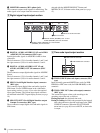
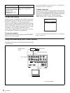
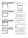
5
Select the formats of video and audio input signal to
be recorded.
Use the INPUT SELECT buttons in the video/audio
input setting section to select the desired signal
formats. Each selection is shown by a lit indicator in
the INPUT signal display section.
Caution
Once you have started recording, you cannot change
the input signal selection.
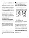
6
Select the audio mode.
Select either two-channel mode (2 CHANNEL) or
four-channel mode (4 CHANNEL) with the REC
MODE menu item (see page 71). The corresponding
indicator lights in the REC MODE display.
Cautions
• Two audio recording modes, with either two
channels at 48 kHz or four channels at 32 kHz, can
be used on this unit. It is not possible to select any
other mode (for example with four channels at 48
kHz).
• If there is a point where the audio mode is switched,
it is not possible to carry out insert editing over a
section including that point.
Selected time data Time data type indicator
Count value of the time
counter
COUNTER
Time code TC
User bit data U-BIT
Video input signal
(input connector)
Corresponding
INPUT
SELECT
button
Lit indicator
in the INPUT
signal display
section
Composite signal
(VIDEO IN: Y/CPST)
VIDEO COMPOSITE
in VIDEO
group
Separated Y/C
signal
(VIDEO IN: Y/CPST
and R−Y/S−C)
VIDEO S VIDEO in
VIDEO group
Component signal
(VIDEO IN: Y/CPST,
R−Y/S−C, and B−Y/
S−Y)
VIDEO Y−R,B in
VIDEO group
SDI signal
(SDI IN)
VIDEO SDI in VIDEO
group
i.LINK-compatible
digital video signal in
DV format
( S400(i.LINK))
VIDEO i.LINK
Internal test video
signal
VIDEO SG in VIDEO
group
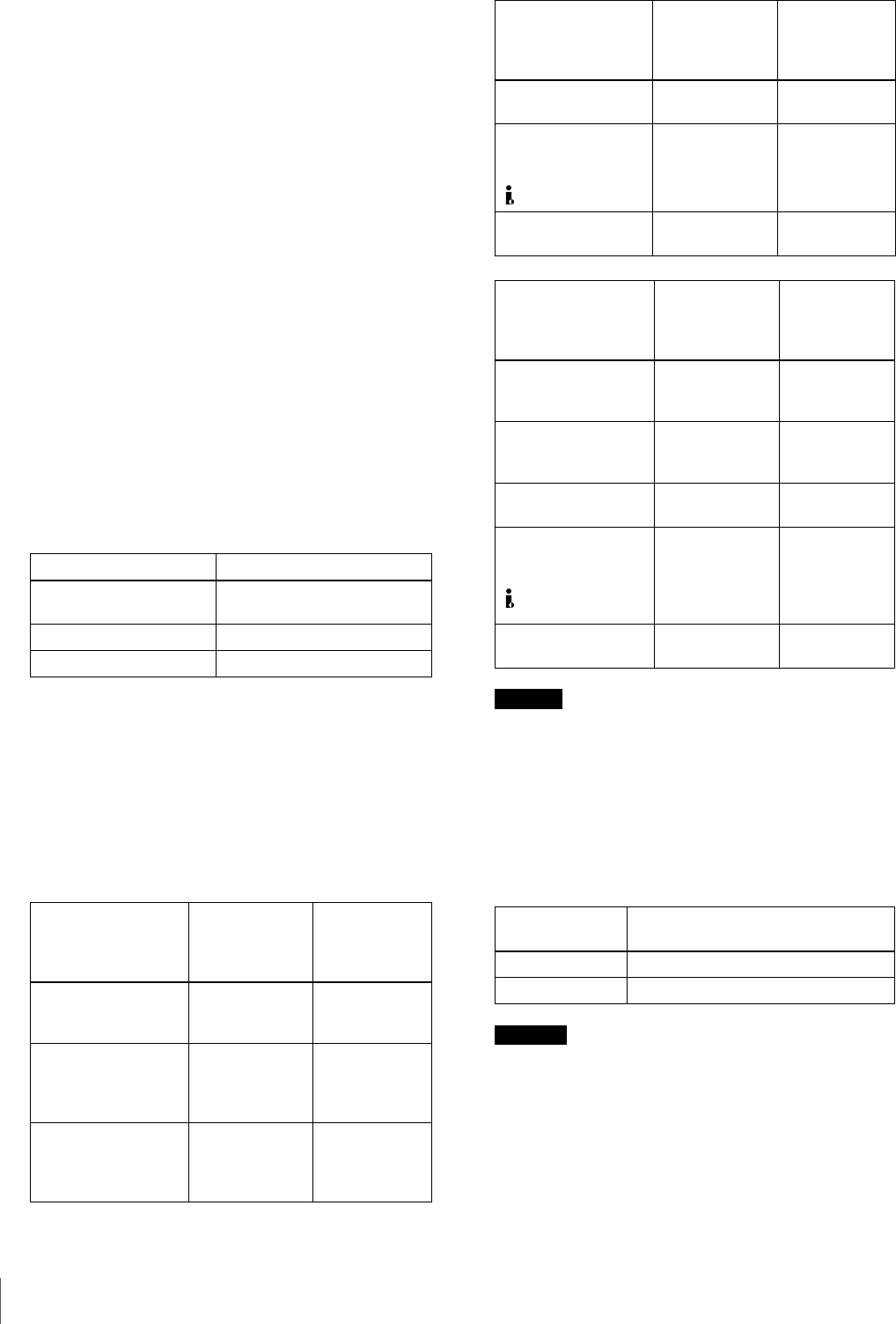
Audio input signal
(input connector)
Corresponding
INPUT SELECT
button
Lit indicator
in the INPUT
signal display
section
Analog signal
(AUDIO IN 1/3 and
AUDIO IN 2/4)
CH1 1/2 and
CH2 3/4
ANALOG in
AUDIO group
AES/EBU signal
(AUDIO (AES/EBU)
IN)
CH1 1/2 and
CH2 3/4
AES/EBU in
AUDIO group
SDI signal
(SDI IN)
CH1 1/2 and
CH2 3/4
SDI in AUDIO
group
i.LINK-compatible
digital audio signal in
DV format
( S400(i.LINK))
automatic
setting
depending on
video input
signals
i.LINK
Internal test audio
signal
CH1 1/2 and
CH2 3/4
SG in AUDIO
group
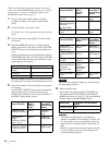
Audio mode Lit indicator in the REC MODE
display
2-channel mode 2CH
4-channel mode 4CH
Video input signal
(input connector)
Corresponding
INPUT
SELECT
button
Lit indicator
in the INPUT
signal display
section